4. Android Application
4.1 Serial Terminal

Connect the board and PC with USB Serial cable, then power on, the terminal will output boot information. The default baudrate is 115200.
su //switch to root mode
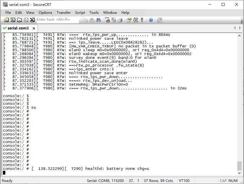
Serial Terminal
4.2 Display
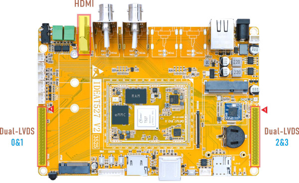
IdeaT527 provides HDMI and 2x dual-LVDS output interfaces. Boardcon firmware supports 2x dual-LVDS display by default.
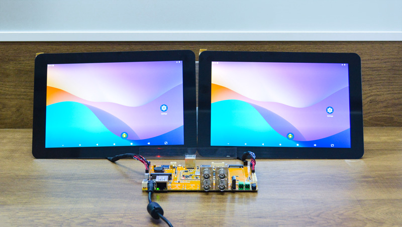
Dual-screen display sync
4.3 USB

IdeaT527 provides 2x USB2.0 connector.
USB0(up) default Host mode.
1su
2echo usb_device > /sys/devices/platform/soc@3000000/10.usbc0/otg_role     //Device mode
3echo usb_host > /sys/devices/platform/soc@3000000/10.usbc0/otg_role       //Host mode
USB2(down) cannot be used with PCIe(SSD) simultaneously. Boardcon Android firmware default USB2 is unavailable.
4.4 Ethernet

Connect the board and router with an Ethernet cable.
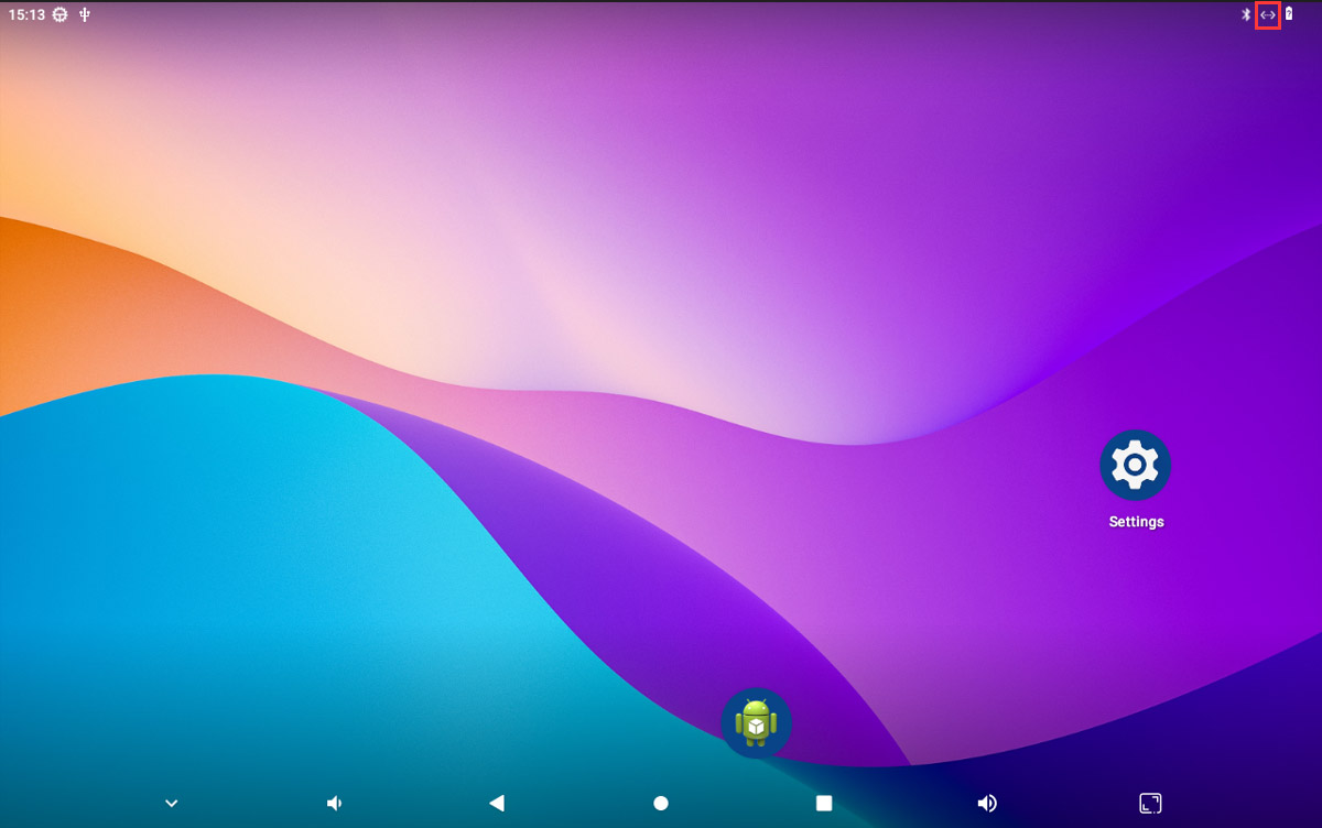
Network connection successful
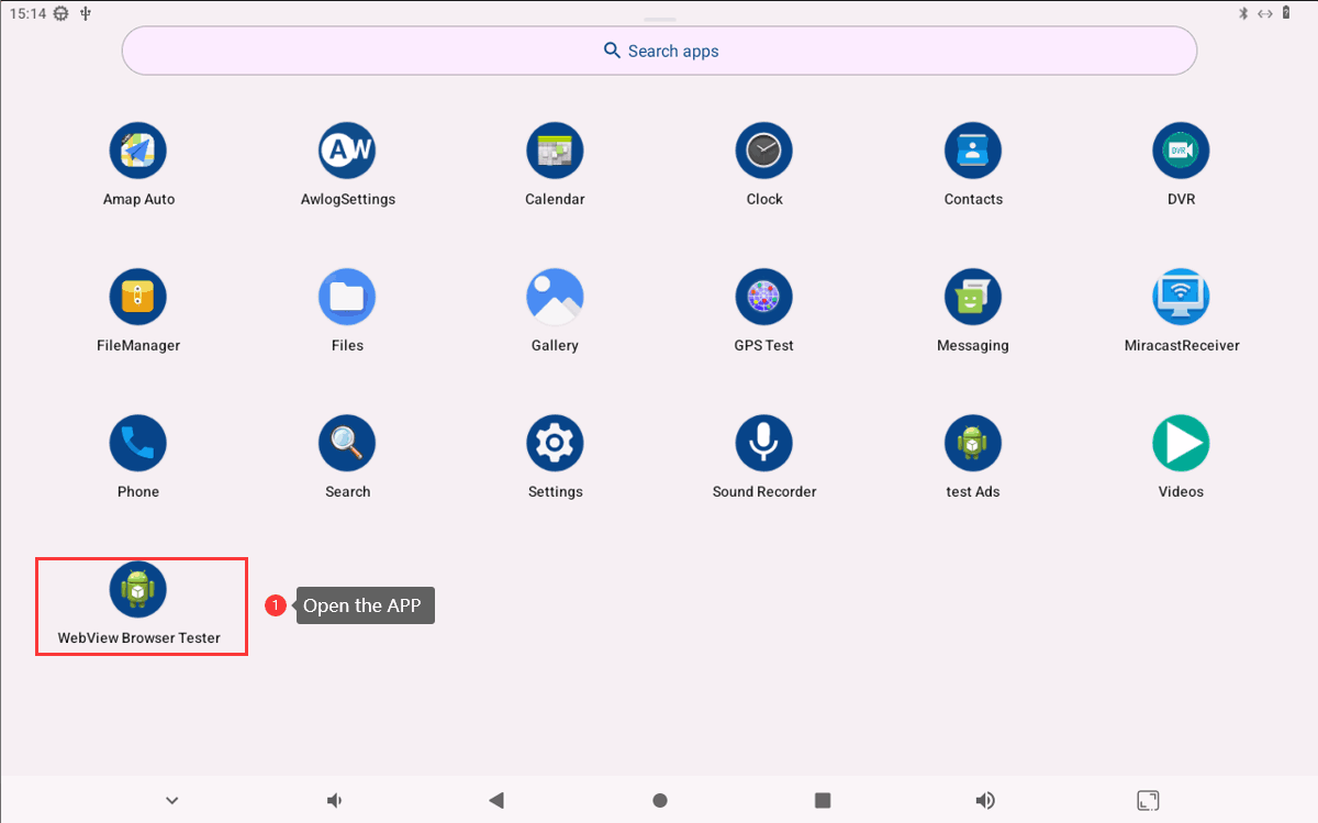
User can open WebView Browser Tester or ping URL/IP to test Network.
1ifconfig
2ping -I eth0 www.armdesigner.com
4.5 4G & GPS
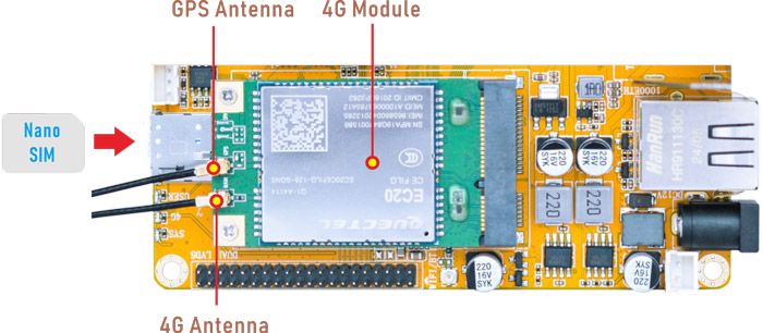
4.5.1 4G
❶ Insert 4G module to mPCIe socket (4G model: EC20).
❷ Connect antenna and insert SIM card.
❸ Power on. The default connection is 4G network.
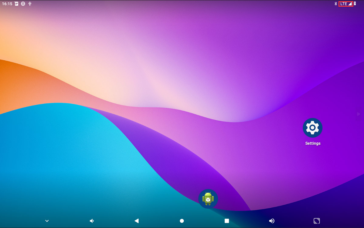
4G network connection
User can open WebView Browser Tester or ping URL/IP to test 4G Network.
1ifconfig
2ping -I wwan0 www.armdesigner.com
4.5.2 GPS
❶ Insert 4G module to mPCIe socket.
❷ Connect GPS antenna.
❸ Power on. Click GPS Test to test.
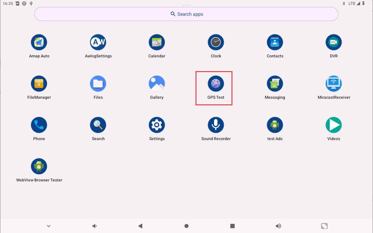
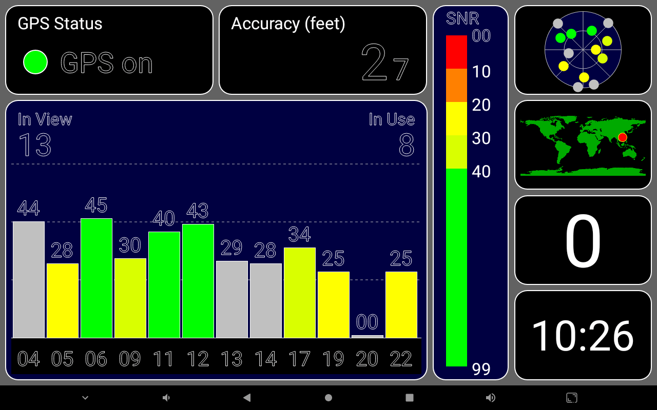
GPS Signal
4.6 SD Card

Click FileManager to view the mounted SD card.
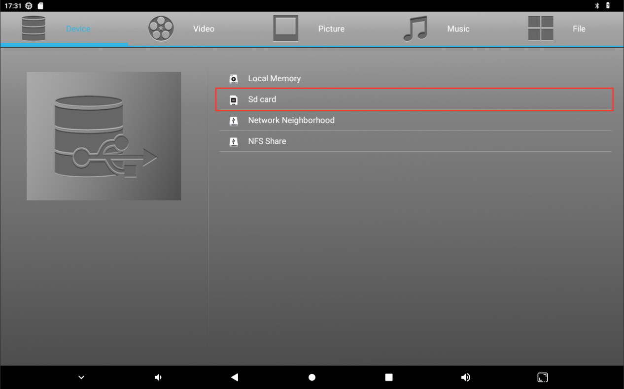
File Manager
4.7 Audio I/O

Audio I/O
4.7.1 Headset

❶ Plug the Microphone into the 3.5mm Audio jack.
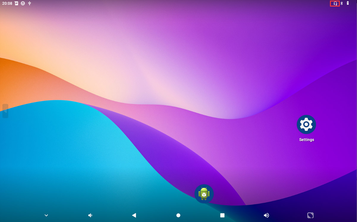
Headset insertion detected
❷ Open Sound Recorder
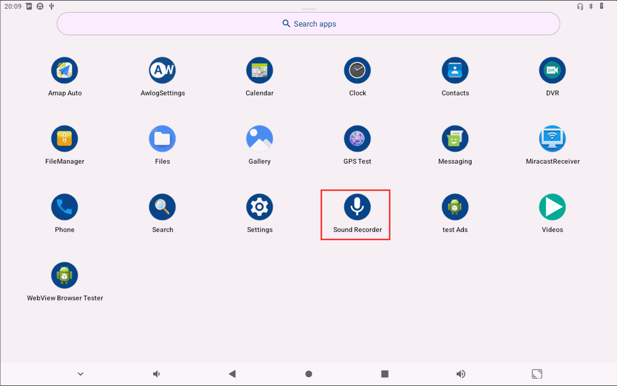
❸ Click Start to start recording.
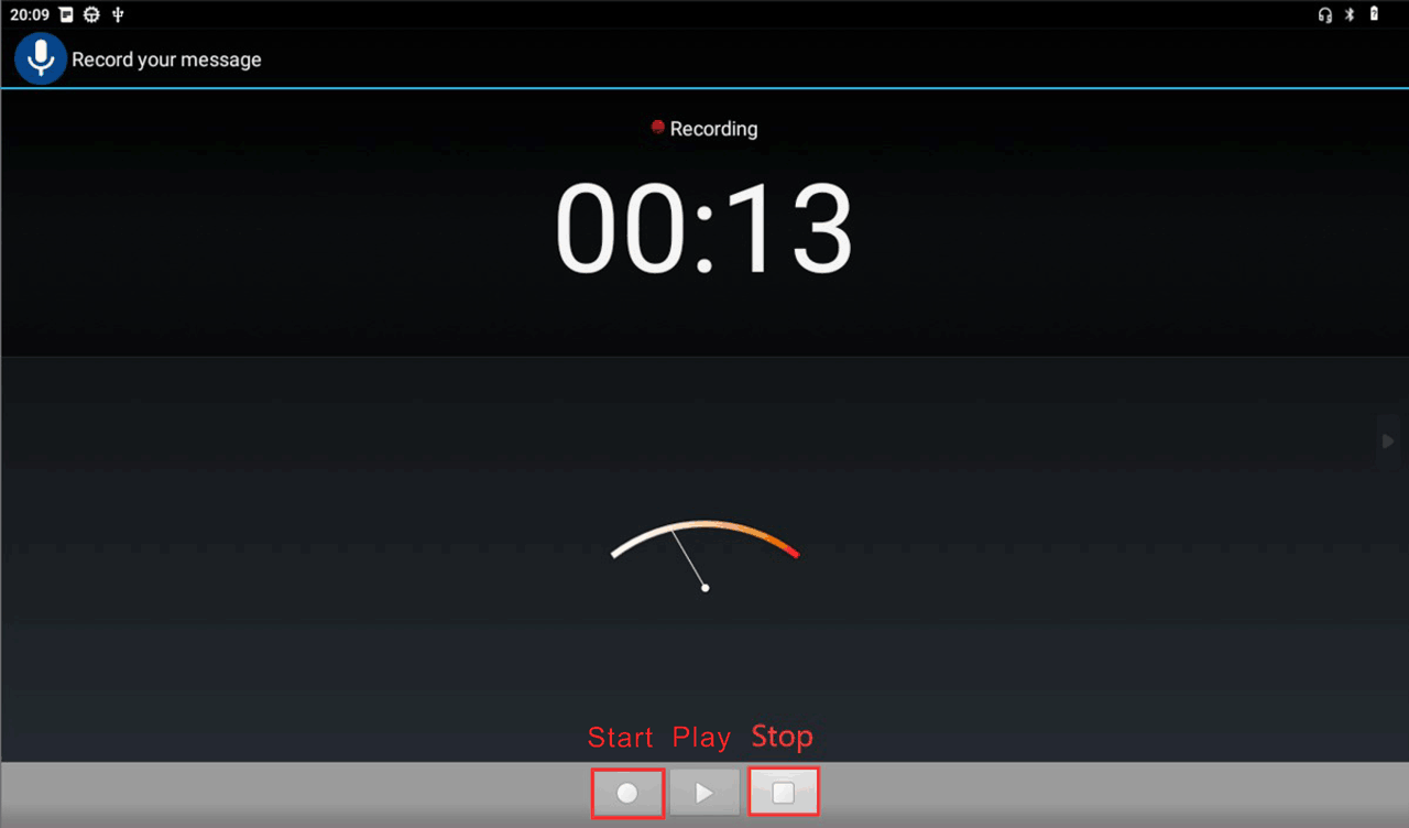
❹ After finish recording, click Stop and play to test recorded file.
4.7.2 MIC

❶ Connect a MIC to the connector (2pin/2.0mm pitch).
❷ Open Sound Recorder
❸ Click Start to start recording.
❹ After finish recording, click Stop and play to test recorded file.
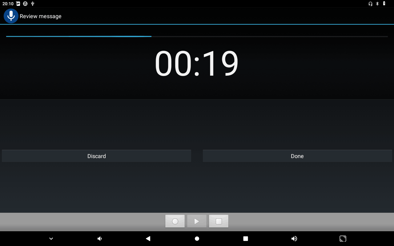
Play recording file
4.7.3 Speaker
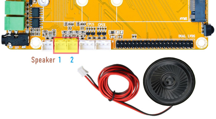
The Speaker connector is 2-pin 2.0mm pitch.
The output priority of headpset is higher than that of speakers. When headset is plugged in, the sound will be output through the headset.
4.8 WiFi & Bluetooth
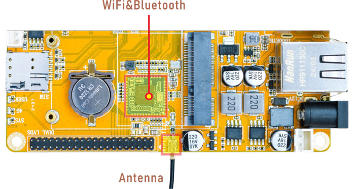
WiFi&BT module
4.8.1 WiFi
❶ Connect the WiFi antenna.
❷ Click Settings -> Network & internet -> Internet -> Wi-Fi -> turn on
❸ Select the SSID from the list of available networks and enter the password.
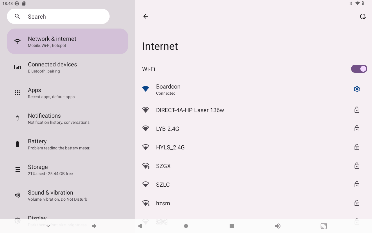
After connected, user can open the browser or ping URL/IP at terminal to test Network.
4.8.2 Bluetooth
Click Settings -> Connected devices -> Pair new device
Select the available device in the list to pair.
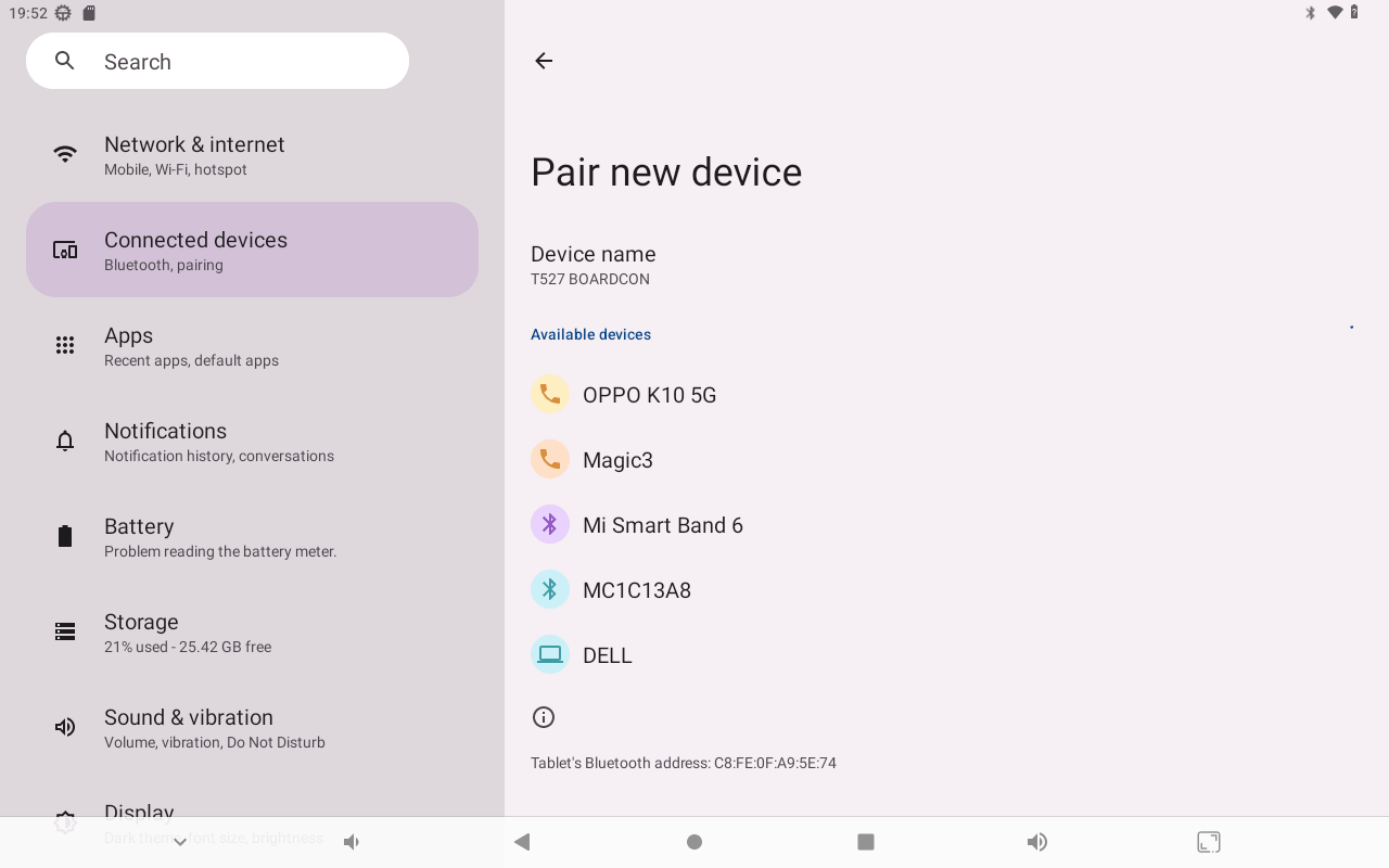
After pairing, devices can connect with each other automatically.
4.9 IR

Configuring the remote control requires modifying the source code \longan\bsp\drivers\ir-rx\sunxi-ir-keymap.h. Use the command getevent to obtain the key value, and fill in the corresponding value into sunxi-ir-keymap.h. After completing all the mapping values, recompile longan and android to generate firmware.
/* Key codes for the x96 remote */
     { 0x118, KEY_POWER },
     { 0x144, KEY_KPDOT },
     { 0x156, KEY_REWIND },
     { 0x15a, KEY_PLAYPAUSE },
     { 0x152, KEY_STOP },
     { 0x154, KEY_FASTFORWARD },
     { 0x143, KEY_SETUP },
     { 0x10f, BTN_TRIGGER_HAPPY14 },
     { 0x114, KEY_VOLUMEDOWN },
     { 0x110, KEY_VOLUMEUP },
     { 0x106, KEY_HOME },
     { 0x140, KEY_BACK },
     { 0x146, KEY_UP },
     { 0x147, KEY_LEFT },
     { 0x155, KEY_OK },
     { 0x115, KEY_RIGHT },
     { 0x116, KEY_DOWN },
     { 0x117, KEY_MENU },
     { 0x104, KEY_EPG },             // mouse
     { 0x14e, KEY_NUMERIC_1 },
     { 0x10d, KEY_NUMERIC_2 },
     { 0x10c, KEY_NUMERIC_3 },
     { 0x14a, KEY_NUMERIC_4 },
     { 0x109, KEY_NUMERIC_5 },
     { 0x108, KEY_NUMERIC_6 },
     { 0x148, KEY_NUMERIC_7 },
     { 0x105, KEY_NUMERIC_8 },
     { 0x107, KEY_NUMERIC_9 },
     { 0x141, KEY_MUTE },
     { 0x101, KEY_NUMERIC_0 },
     { 0x142, KEY_BACKSPACE },
4.10 Camera

❶ Connect the cameras to the development board (four cameras for example).
❷ Click DVR APP.
❸ Select preview channels.
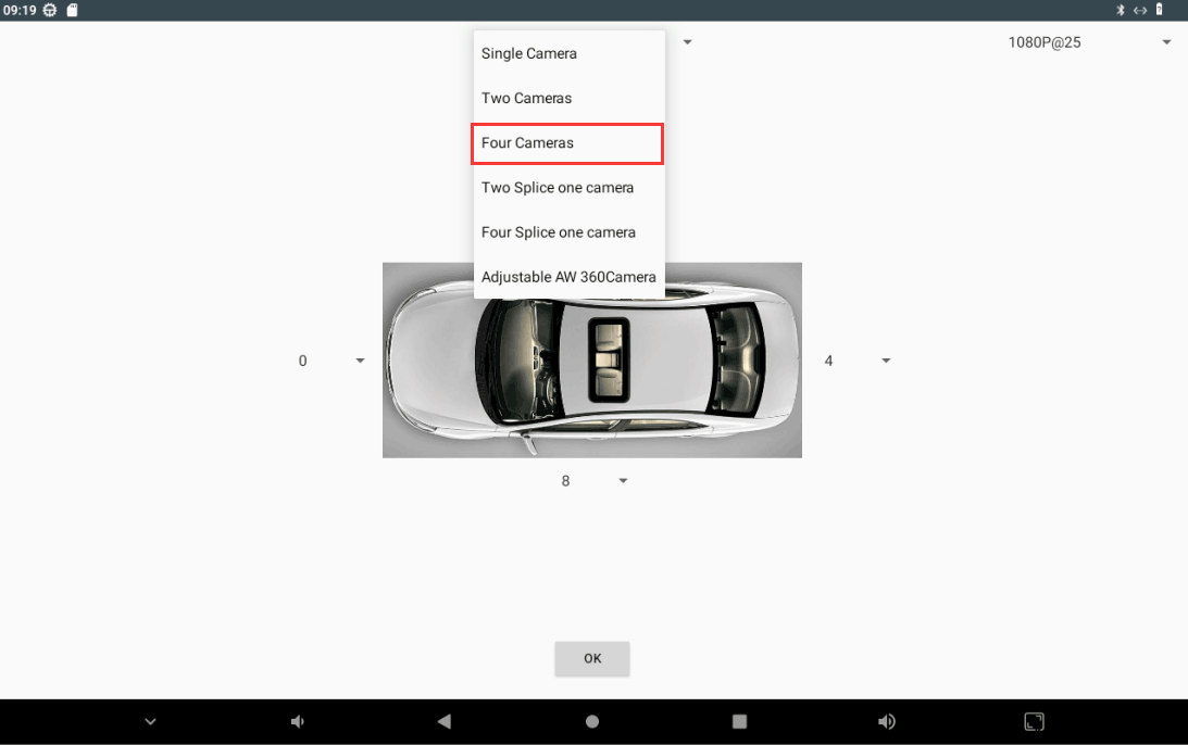
Select Camera preview channels
❹ Select camera resolution (Incorrect resolution will result in no display).
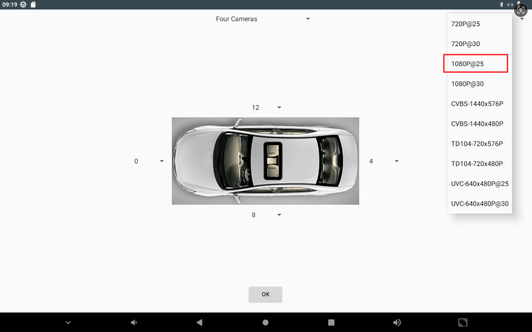
Select Camera resolution
Note
If use CVBS camera, please select TD104-720x576p
❺ Select preview device.
1ls /dev/video* //view device ID
The corresponding device ID is 0, 4, 8, 12.
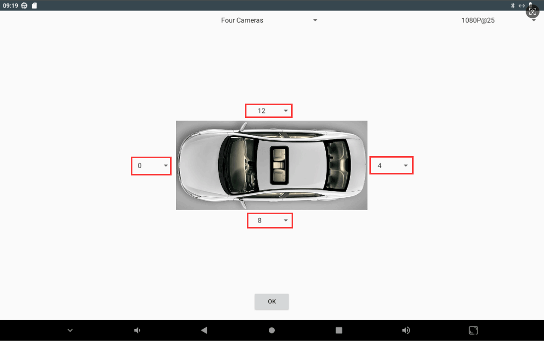
Select device
❻ Click OK
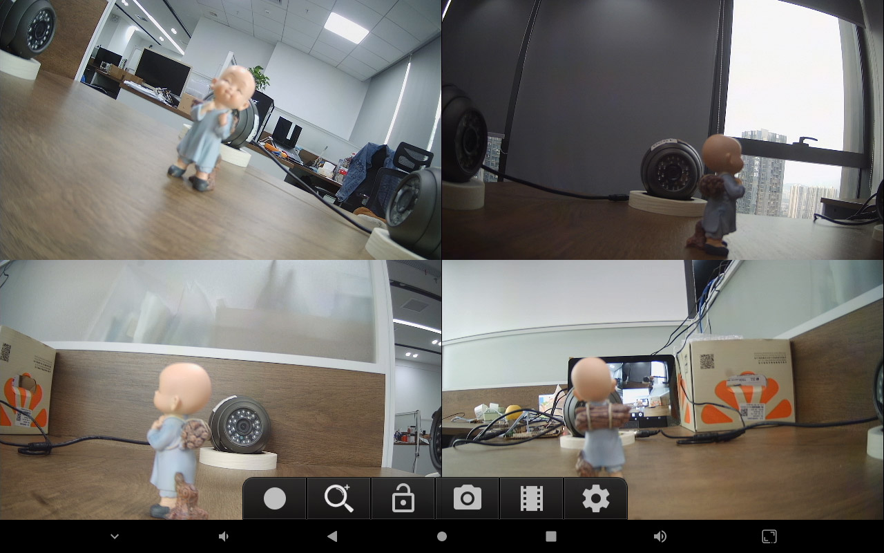
Preview effect
4.11 RS485

❶ Connect PC and board with USB-to-RS485 adapter.

RS485 connection
❷ Open the Serial Terminal of board and RS485 adapter respectively. Set the baud rate to 115200.
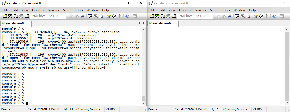
❸ Execute the following commands on the terminal serial ports of board.
1su
2com /dev/ttyAS3 115200 8 0 1
❹ Input character to test RS485 communication.
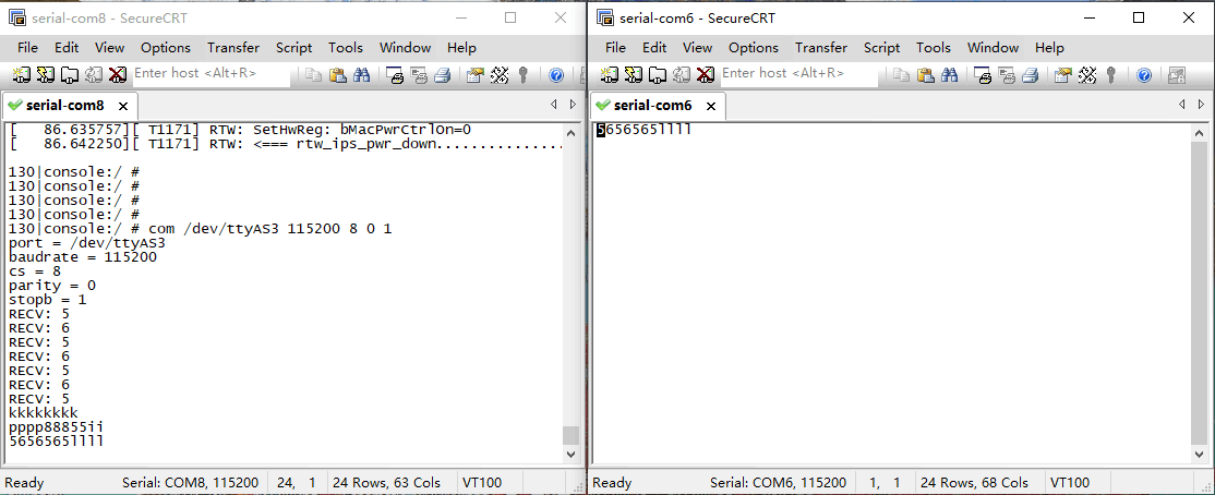
4.12 CAN

The device name for CAN0 is awlink0, CAN1 is awlink1.
❶ Connect PC and board with USB-to-CAN adapter.
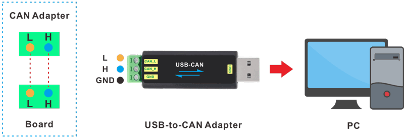
CAN connection
❷ Open the CAN application and set the baudrate to 1000000 on PC.
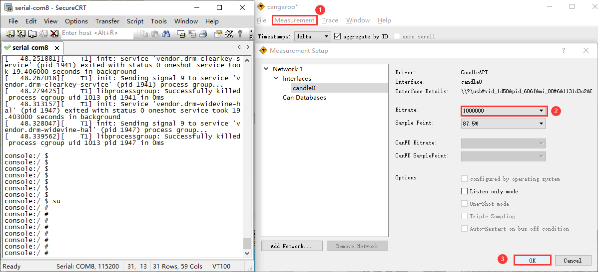
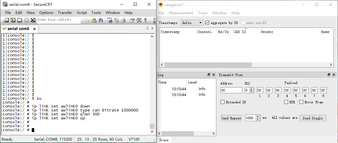
❸ Execute commands on Serial Terminal to configure and start the CAN network.
1su
2ip link set awlink0 down
3ip link set awlink0 type can bitrate 1000000
4ip link set awlink0 qlen 300
5ip link set awlink0 up
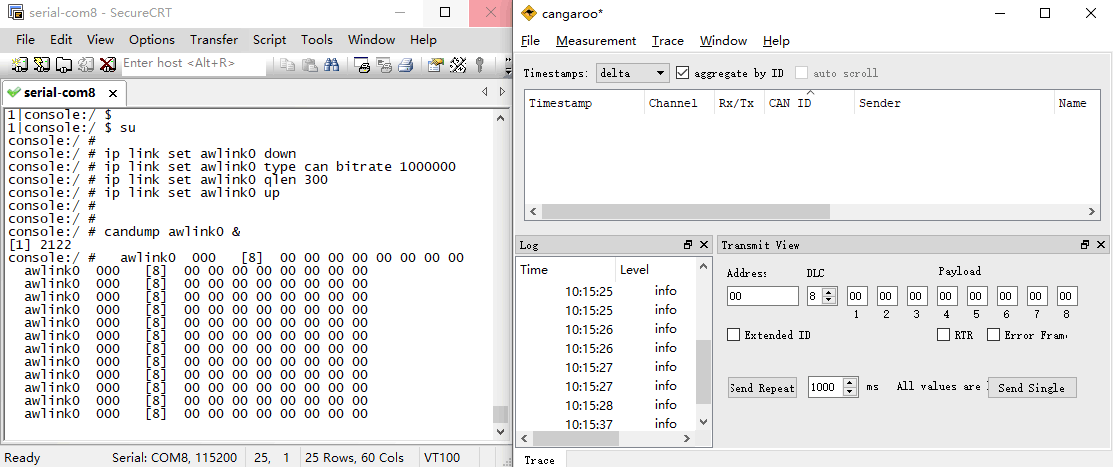
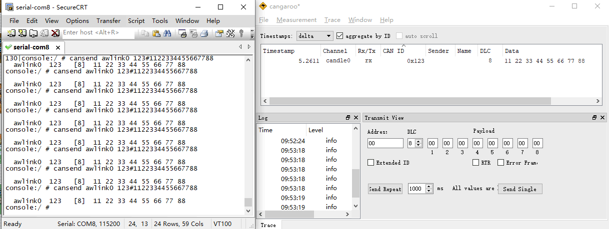
❹ Configure CAN as receiver.
1candump awlink0 &
❺ Set CAN as Transmitter.
1cansend awlink0 123#1122334455667788
4.13 M.2 SSD

❶ Connect SSD to the M.2 socket, then power on.
❷ Mount SSD.
1su
2mkdir /mnt/ssd1
3mount /dev/block/nvme0n1 /mnt/ssd1
4ls /mnt/ssd1
Note
IdeaT527 SSD on Android 13 only supports the ext4 format. If the device is not in ext4 format, user can format it on the board. The formatting will result in permanent loss of all files on the device, please handle with caution.
mke2fs -t ext4 /dev/block/nvme0n1 //format SSD to ext4
4.14 RTC
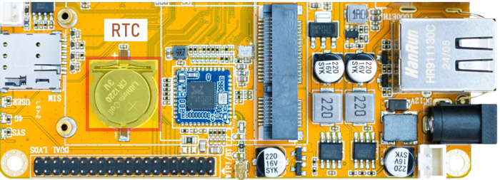
❶ Insert a CR1220 battery before test. It keeps the time running when the main power is off.
❷ Set date and time manually.
1su
2date -s "2024-10-31 15:22:30"           //set system date
3hwclock -w                              //set the hardware clock to current system time
4hwclock                                 //display date and time
❸ Power off. Wait for a moment, power on again, and then execute the command hwclock, check whether the time is saved.
If connected to the internet, the time will automatically synchronize with the network time.