6. Android Application
6.1 Display
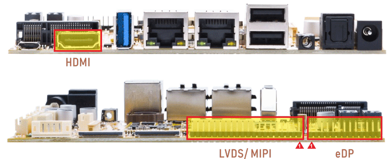
Connect the board and monitor, then start up. EM3568 supports LVDS and HDMI dual-display. Audio output priority: Headset > HDMI > Speaker.
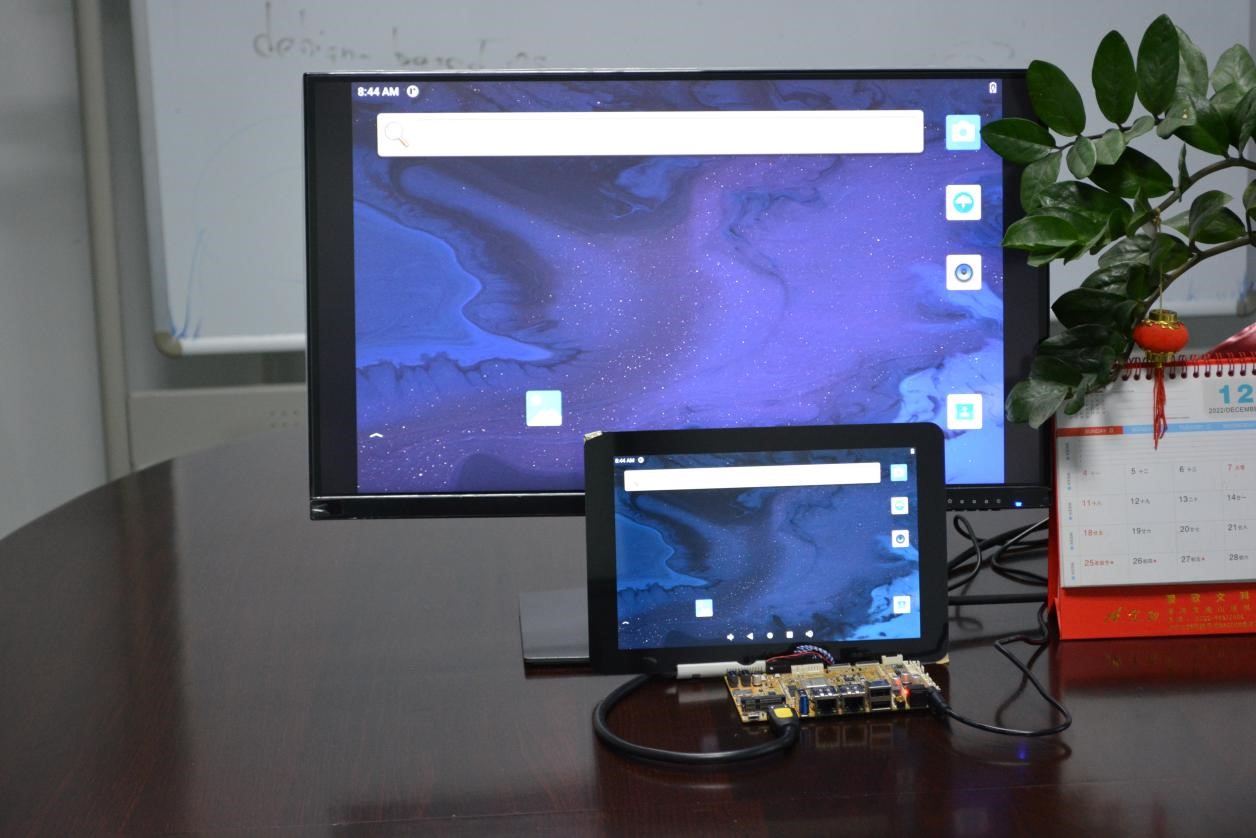
Display synchronization
6.2 ADB
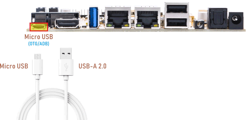
The micro USB is mainly used for firmware upgrades and ADB function.
ADB is the command-line debugging tool. It can use for system logs, uploading and downloading the files, installing the applications, etc.
❶ connect the board and PC host with Micro USB cable.
❷ install ADB driver on Windows system.
❸ press Windows + R to open the Run program. Type cmd and press Enter
❹ execute commands to enable ADB and test.
Push the file com located in PC E:\EM3568\Tool\Test\ to the board for example:
1adb root
2adb remount
3adb push E:\EM3568\Tool\Test\com /system
4adb shell
5chmod 777 /system/com    //modify com properties
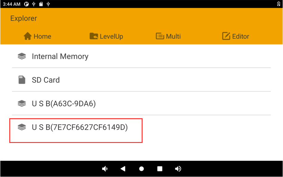
6.3 USB Host
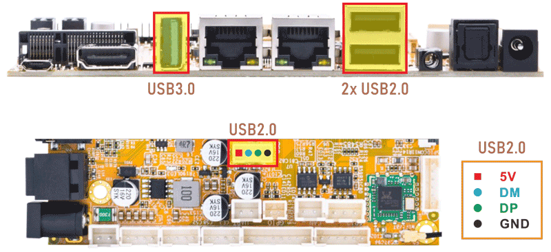
The USB2.0/3.0 Host can be used to connect USB mouse, USB keyboard, U-Disk or other USB devices. Click Explorer icon to view the mounted U-disk.
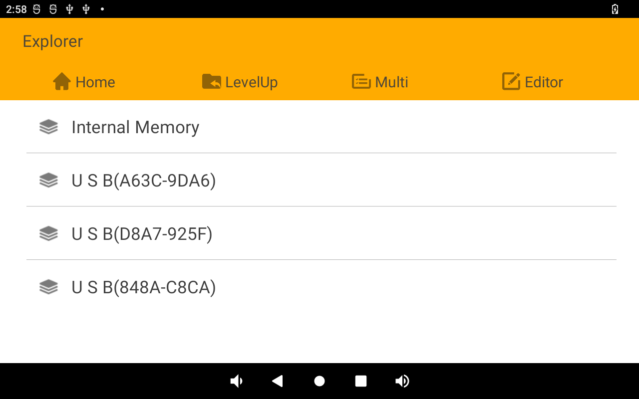
Mounted U-disk
USB3.0 Superspeed detected:
console:/ #
[  130.358199] healthd: battery l=50 v=3 t=2.6 h=2 st=3 fc=100 chg=au
[  146.097060] usb 6-1: new SuperSpeed Gen 1 USB device number 2 using xhci-hcd
[  146.116032] usb 6-1: New USB device found, idVendor=3535, idProduct=6300, bcdDevice= 1.10
[  146.116104] usb 6-1: New USB device strings: Mfr=1, Product=2, SerialNumber=3
[  146.116131] usb 6-1: Product: U330
[  146.116156] usb 6-1: Manufacturer: aigo
[  146.116179] usb 6-1: SerialNumber: 52A7B285B4956ADF
[  146.121295] usb-storage 6-1:1.0: USB Mass Storage device detected
6.4 SD Card
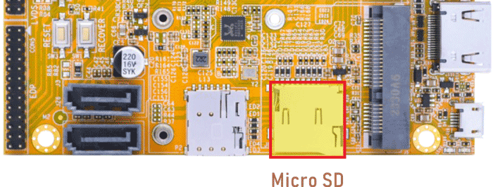
EM3568 supports SD Hot-plug. Click Explorer icon to view the mounted SD card.
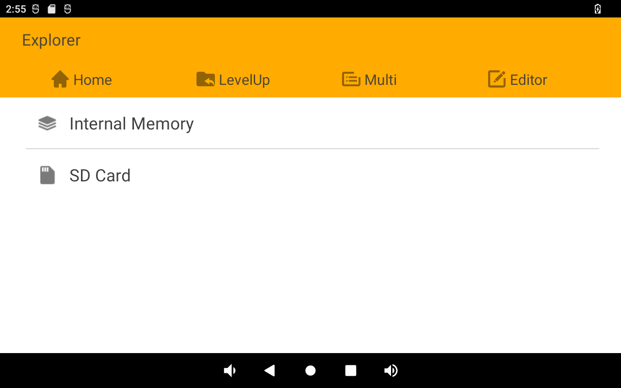
Mounted SD card
6.5 Ethernet
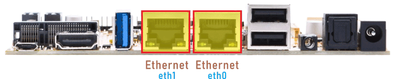
Connect the board and router with an Ethernet cable (default DHCP=Yes). User can ping URL/IP at terminal, or open the browser to test Network. If two network ports are used at the same time, eth0 is connected to Internet, and eth1 is connected to LAN.
1ifconfig
2ping -I eth0 www.boardcon.com
3ping -I eth1 192.168.0.2
console:/ # ifconfig
eth1      Link encap:Ethernet  HWaddr a6:3f:3c:a9:da:66  Driver rk_gmac-dwmac
          inet addr:192.168.0.112  Bcast:192.168.0.255  Mask:255.255.255.0
          inet6 addr: fe80::56c3:7cfc:ab09:2ba1/64 Scope: Link
          UP BROADCAST RUNNING MULTICAST  MTU:1500  Metric:1
          RX packets:716 errors:0 dropped:13 overruns:0 frame:0
          TX packets:255 errors:0 dropped:0 overruns:0 carrier:0
          collisions:0 txqueuelen:1000
          RX bytes:108518 TX bytes:29920
          Interrupt:47

dummy0    Link encap:Ethernet  HWaddr c6:e4:e8:07:d1:08
          inet6 addr: fe80::c4e4:e8ff:fe07:d108/64 Scope: Link
          UP BROADCAST RUNNING NOARP  MTU:1500  Metric:1
          RX packets:0 errors:0 dropped:0 overruns:0 frame:0
          TX packets:6 errors:0 dropped:0 overruns:0 carrier:0
          collisions:0 txqueuelen:1000
          RX bytes:0 TX bytes:420

eth0      Link encap:Ethernet  HWaddr aa:3f:3c:a9:da:66  Driver rk_gmac-dwmac
          inet addr:192.168.0.108  Bcast:192.168.0.255  Mask:255.255.255.0
          inet6 addr: fe80::35fb:6a8d:85b4:8bad/64 Scope: Link
          UP BROADCAST RUNNING MULTICAST  MTU:1500  Metric:1
          RX packets:808 errors:0 dropped:10 overruns:0 frame:0
          TX packets:260 errors:0 dropped:0 overruns:0 carrier:0
          collisions:0 txqueuelen:1000
          RX bytes:117724 TX bytes:29904
          Interrupt:42

lo        Link encap:Local Loopback
          inet addr:127.0.0.1  Mask:255.0.0.0
          inet6 addr: ::1/128 Scope: Host
          UP LOOPBACK RUNNING  MTU:65536  Metric:1
          RX packets:12 errors:0 dropped:0 overruns:0 frame:0
          TX packets:12 errors:0 dropped:0 overruns:0 carrier:0
          collisions:0 txqueuelen:1000
          RX bytes:1344 TX bytes:1344
console:/ # ping -I eth0 www.boardcon.com
PING www.boardcon.com (67.222.54.196) from 192.168.0.108 eth0: 56(84) bytes of data.
64 bytes from 67-222-54-196.unifiedlayer.com (67.222.54.196): icmp_seq=1 ttl=48 time=188 ms
64 bytes from 67-222-54-196.unifiedlayer.com (67.222.54.196): icmp_seq=2 ttl=48 time=187 ms
64 bytes from 67-222-54-196.unifiedlayer.com (67.222.54.196): icmp_seq=3 ttl=48 time=188 ms
64 bytes from 67-222-54-196.unifiedlayer.com (67.222.54.196): icmp_seq=3 ttl=48 time=188 ms
64 bytes from 67-222-54-196.unifiedlayer.com (67.222.54.196): icmp_seq=3 ttl=48 time=189 ms
^C
--- www.boardcon.com ping statistics ---
5 packets transmitted, 5 received, 0% packet loss, time 4013ms
rtt min/avg/max/mdev = 187.842/188.636/189.916/0.980 ms

console:/ # ping -I eth1 192.168.0.2
PING 192.168.0.2 (192.168.0.2) from 192.168.0.112 eth1: 56(84) bytes of data.
64 bytes from 192.168.0.2: icmp_seq=1 ttl=64 time=1.86 ms
64 bytes from 192.168.0.2: icmp_seq=2 ttl=64 time=1.68 ms
64 bytes from 192.168.0.2: icmp_seq=3 ttl=64 time=1.75 ms
64 bytes from 192.168.0.2: icmp_seq=4 ttl=64 time=1.88 ms
^C
--- 192.168.0.2 ping statistics ---
4 packets transmitted, 4 received, 0% packet loss, time 3004ms
rtt min/avg/max/mdev = 1.681/1.799/1.887/0.083 ms
6.6 Audio I/O
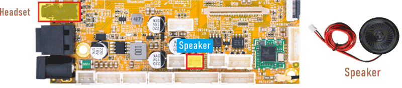
❶ Plug the headset into the 3.5mm audio jack.
❷ Open the APP Sound Recorder in Android.
❸ Click Start button to start recording.
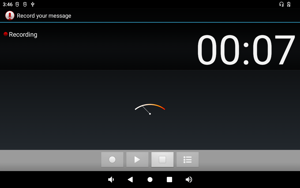
After finish recording, click Stop and Save to store file. The default storage path is Internal Memory/Recordings
Audio output priority: Headset > Speaker.
6.7 RTC
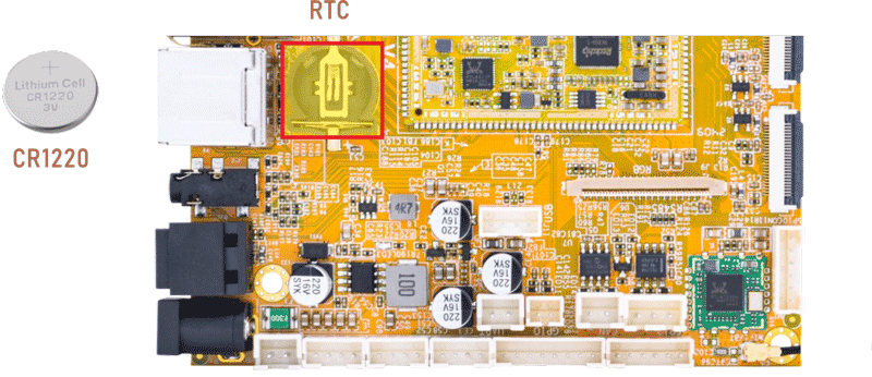
❶ insert a CR1220 battery before test. It keeps the time running when the main power is off.
❷ set date and time manually.
1date "2024-12-31 18:07:00"
2hwclock -w
3hwclock
console:/ # date "2024-12-31 18:07:00"
Tue Dec 31 18:07:00 GMT 2024
console:/ # hwclock -w
console:/ # hwclock
2024-12-31 18:07:06+0000
console:/ # hwclock
2024-12-31 18:07:16+0000
6.8 WiFi & Bluetooth
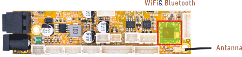
6.8.1 WiFi
❶ connect the WiFi antenna.
❷ click Settings -> Network & internet -> Wi-Fi -> turn on
❸ select the SSID from the list of available networks and enter the password.
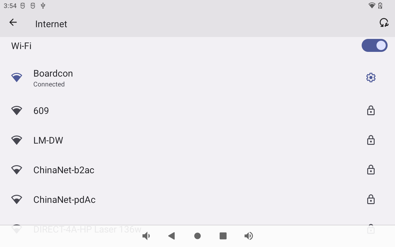
After connected, user can ping URL/IP at terminal, or open the browser to test Network.
1ifconfig
2ping -I wlan0 www.boardcon.com
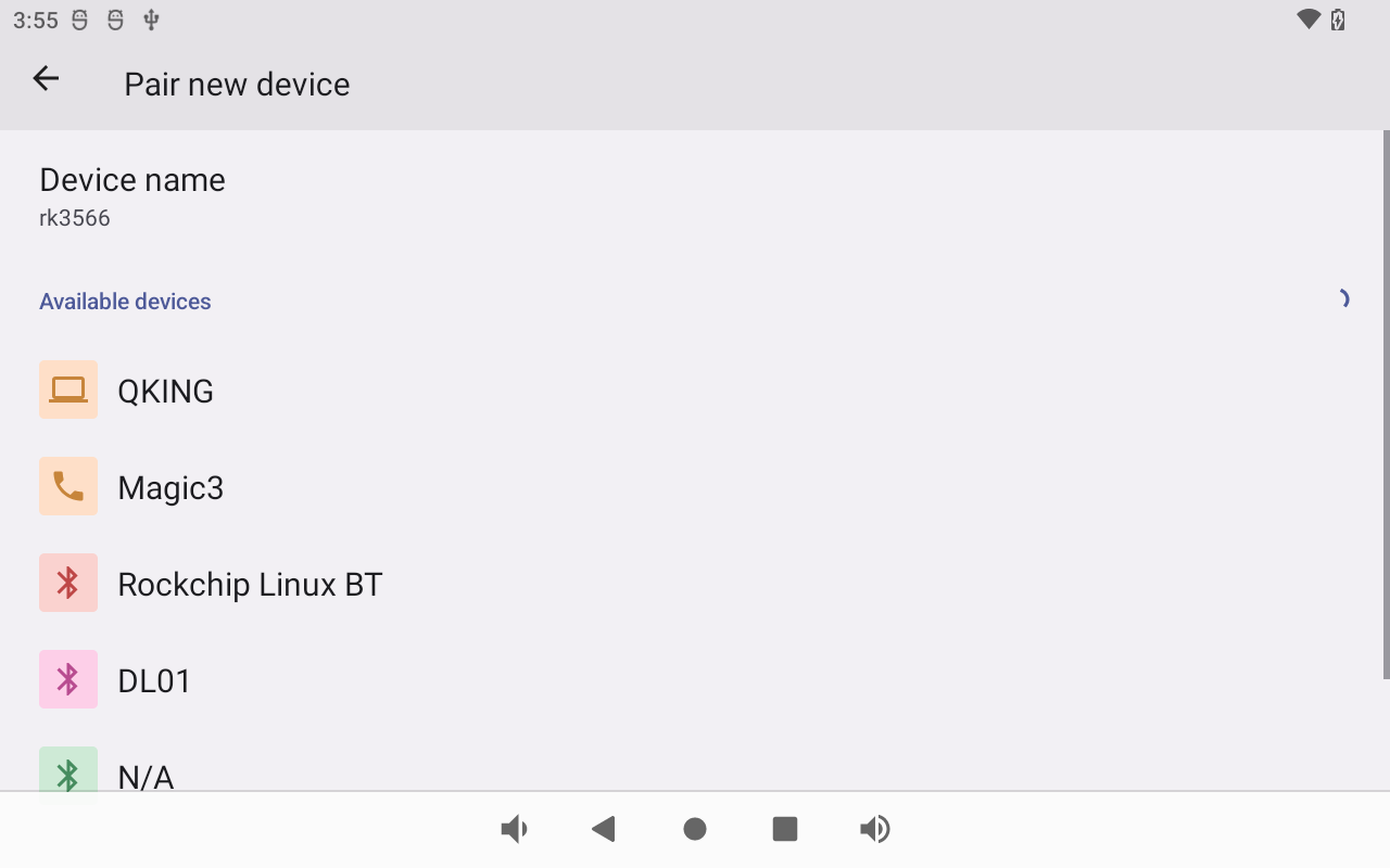
6.8.2 Bluetooth
Click Settings -> Connected devices -> Pair new device
Select the available device in the list to pair.
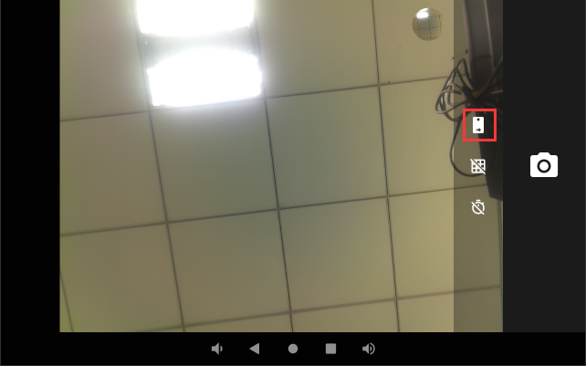
6.9 Camera
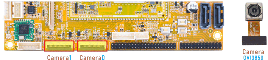
Connect the camera module (OV13850) to the development board before power on, then click the camera APP to test.
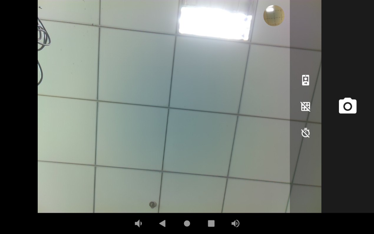
If two cameras are connected, user can switch between the front and rear cameras by clicking on the icon.
6.10 CAN
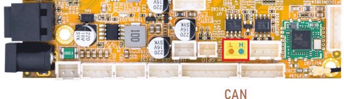
❶ Connect the CAN ports of Board A and B with the test line.
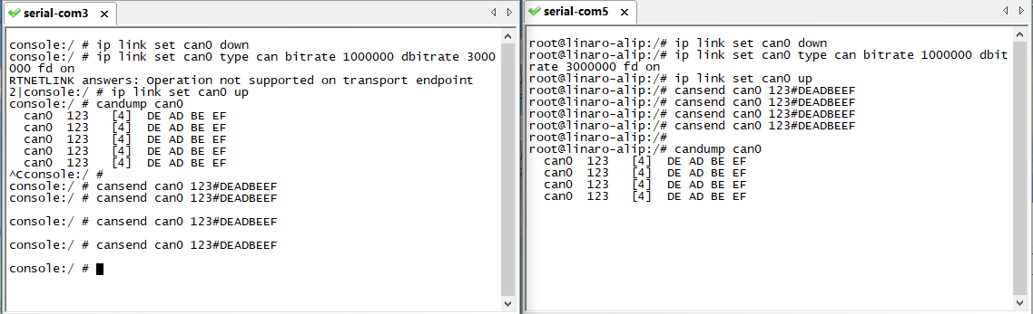
❷ execute the commands on the serial terminal of board A and board B respectively.
ip link set can0 down
ip link set can0 type can bitrate 1000000 dbitrate 3000000 fd on
ip link set can0 up
candump can0                      //set CAN0 as receive
cansend can0 123#DEADBEEF         //CAN0 send characters 0xDE 0xAD 0xBE 0xEF
6.11 RS485
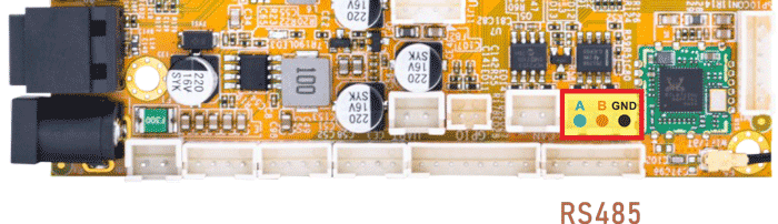
This test method is for reference only.
❶ Connect the RS485 ports of Board A and B with the test line.
❷ Push the file “com” to the board via ADB
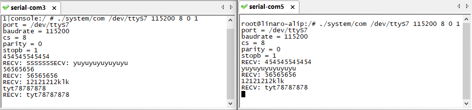
❸ Execute the command on the terminal serial ports of board A and board B respectively.
./system/com /dev/ttyS7 115200 8 0 1
❹ Input character to test RS485 communication.
6.12 UART
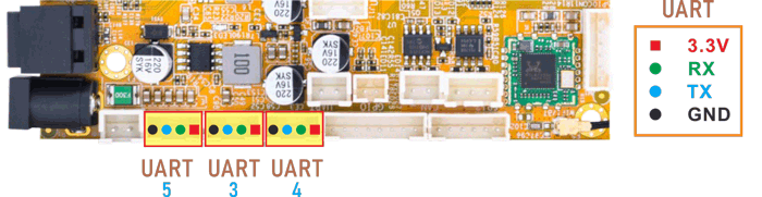
The UART loopback test is for reference only.
❶ Push the file “com” to the board via ADB
❷ Connect the transmit(TX) pin to the receive(RX) pin of UART.
❸ After executes the command, input character to test UART.
1./system/com /dev/ttyS3 115200 8 0 1 //test UART3
console:/ # ./system/com /dev/ttyS3 115200 8 0 1
port = /dev/ttyS3
baudrate = 115200
cs = 8
parity = 0
stopb = 1
aaaaaaaaaaaa
RECV: aaaaaaaaaaaa
❹ Press Ctrl + C to exit UART3 testing.
Execute command to test UART4 or UART5.
./system/com /dev/ttyS4 115200 8 0 1   //test UART4
./system/com /dev/ttyS5 115200 8 0 1   //test UART5
6.13 SATA
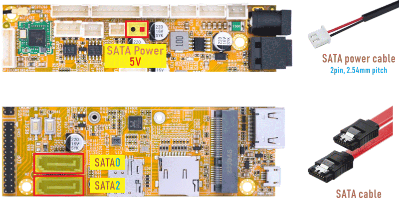
❶ Connect the SATA0 (6Gb/s) or SATA2 (3Gb/s) and the SATA power.
❷ Power on.
❸ Click Explorer icon to view the mounted SATA.
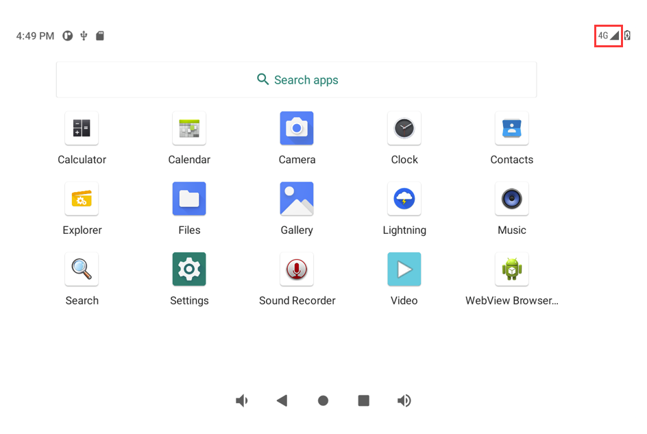
6.14 4G
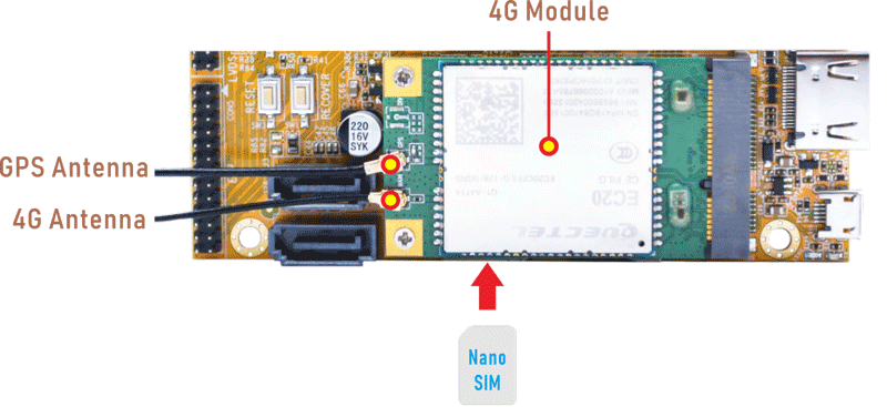
❶ Insert 4G module to mPCIe slot (4G model: EC20).
❷ Connect antenna and insert SIM card.
❸ Power on.
The default network connection is 4G LTE.