6. Android Application
6.1 Display
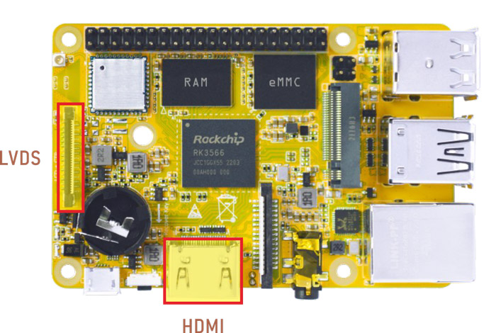
Display IO
Connect the board and monitor with a HDMI cable, then start up.
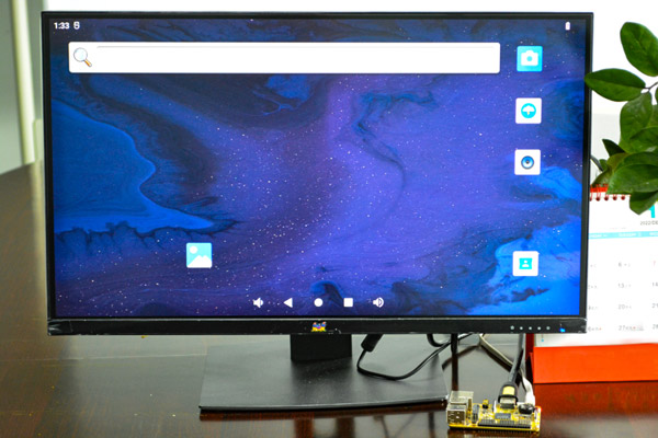
HDMI Display
For 4K video files in H.265/H.264/VP9 format, both HDMI and LVDS can play streaming, but only HDMI can output 4K 60fps.
Audio output priority: headphone is higher than HDMI.
Note
HDMI and LVDS do not support simultaneous display. The Boardcon factory default HDMI display. If change to LVDS LCD, please reflash the corresponding boot.img
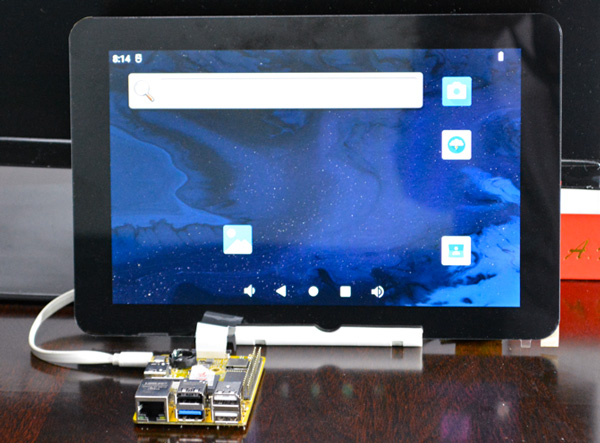
LVDS display
6.2 Audio IO
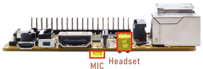
Recording priority: headset recording is higher than MIC.
1tinymix -D 1 14 0
2tinymix -D 1 15 0
1tinymix -D 1 14 1
2tinymix -D 1 15 1
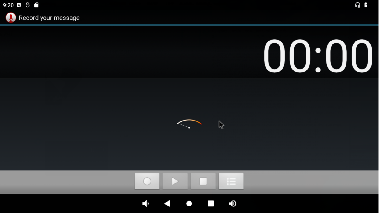
Recording
6.3 Micro SD
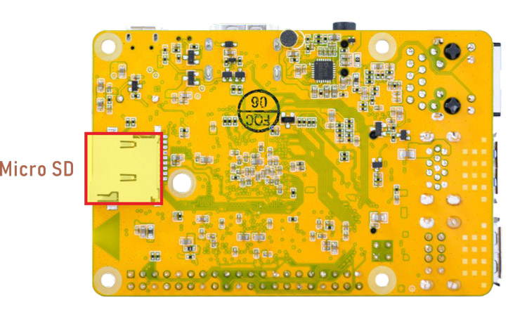
Micro SD
Compact3566 supports SD Hot-plug.
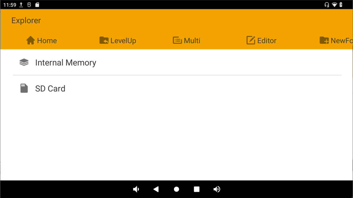
Mounted SD
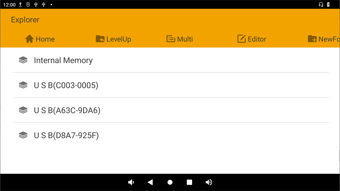
6.4 USB Host
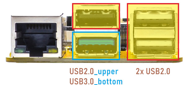
The USB2.0/3.0 Host can be used to connect USB mouse, USB keyboard, U-Disk or other USB devices.
USB Device
The USB3.0 default supports Superspeed.
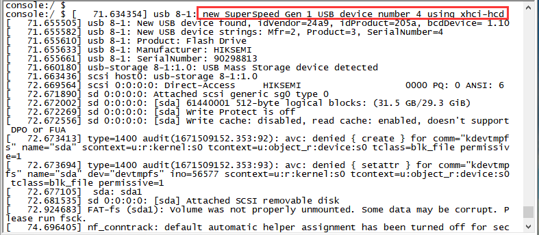
Superspeed
6.5 M.2 SSD
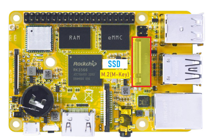
M.2 SSD
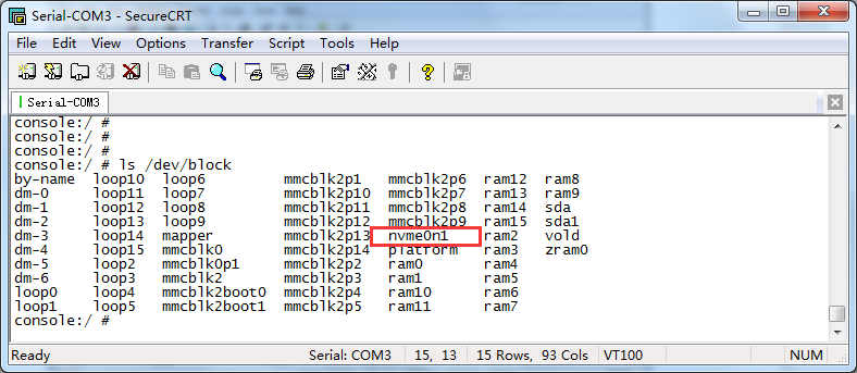
Compact3566 only supports ext4 format. Format SSD to ext4 file system on ubuntu system
❶ view the SSD device name.
1ls /dev/block
❷ format SSD on Ubuntu system.
1mke2fs -t ext4 /dev/block/nvme0n1
❸ mount SSD.
1mkdir /data/ssd
2mount -t ext4 /dev/block/nvme0n1 /data/ssd
3ls /data/ssd
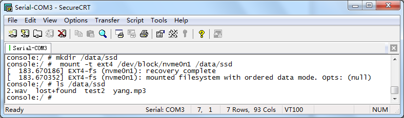
If the SSD is auto-mounted, execute the command to test:
1ls /run/media/nvme0n1
6.6 WiFi & Bluehost
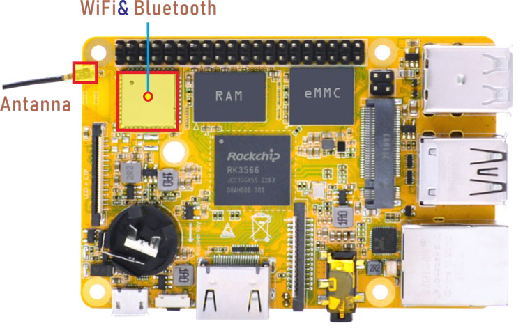
WiFi & Bluehost
6.6.1 WiFi
❶ connect the WiFi antenna.
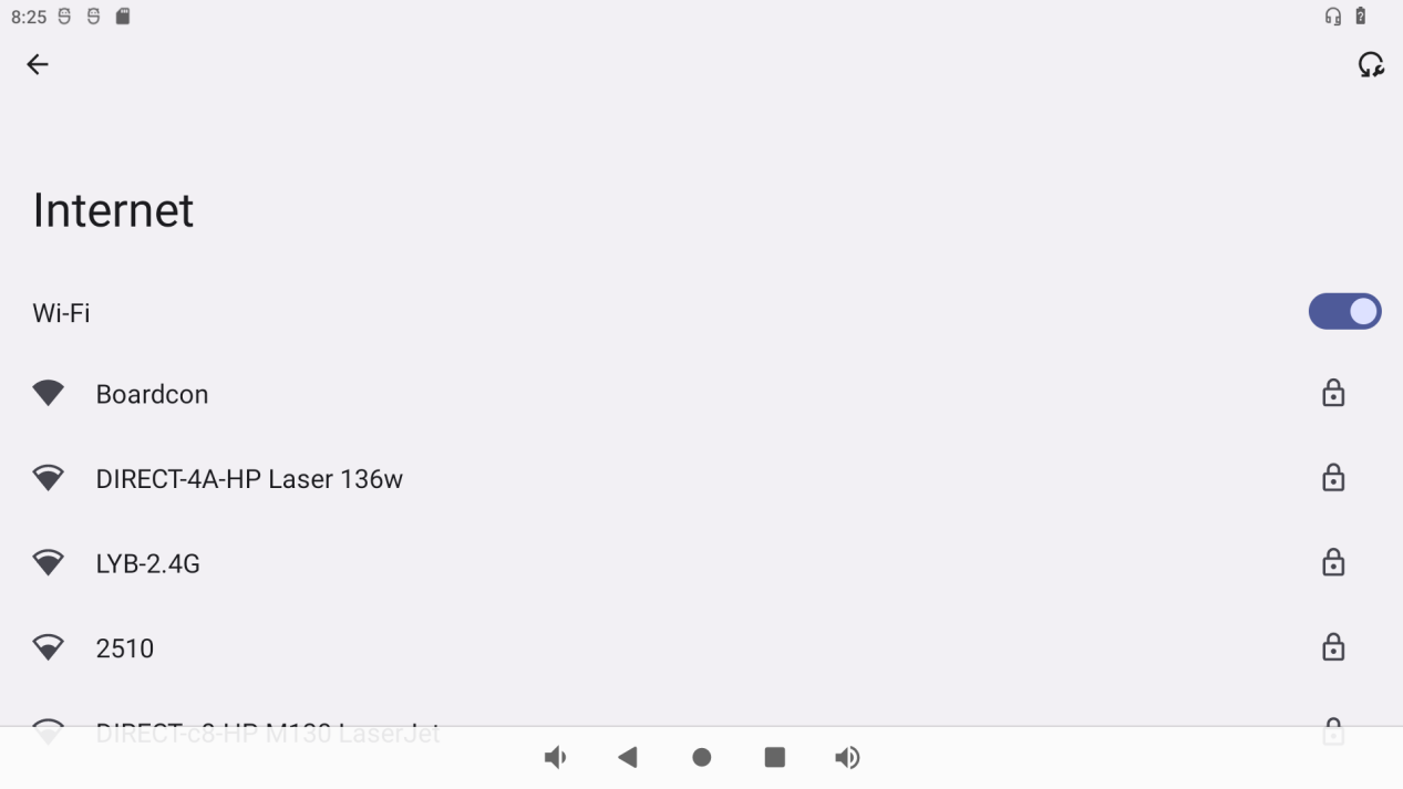
❷ click Settings -> Network & internet -> Wi-Fi -> turn on
❸ select the SSID from the list of available networks and enter the password.
After connected, user can ping URL/IP at terminal, or open the browser to test Network.
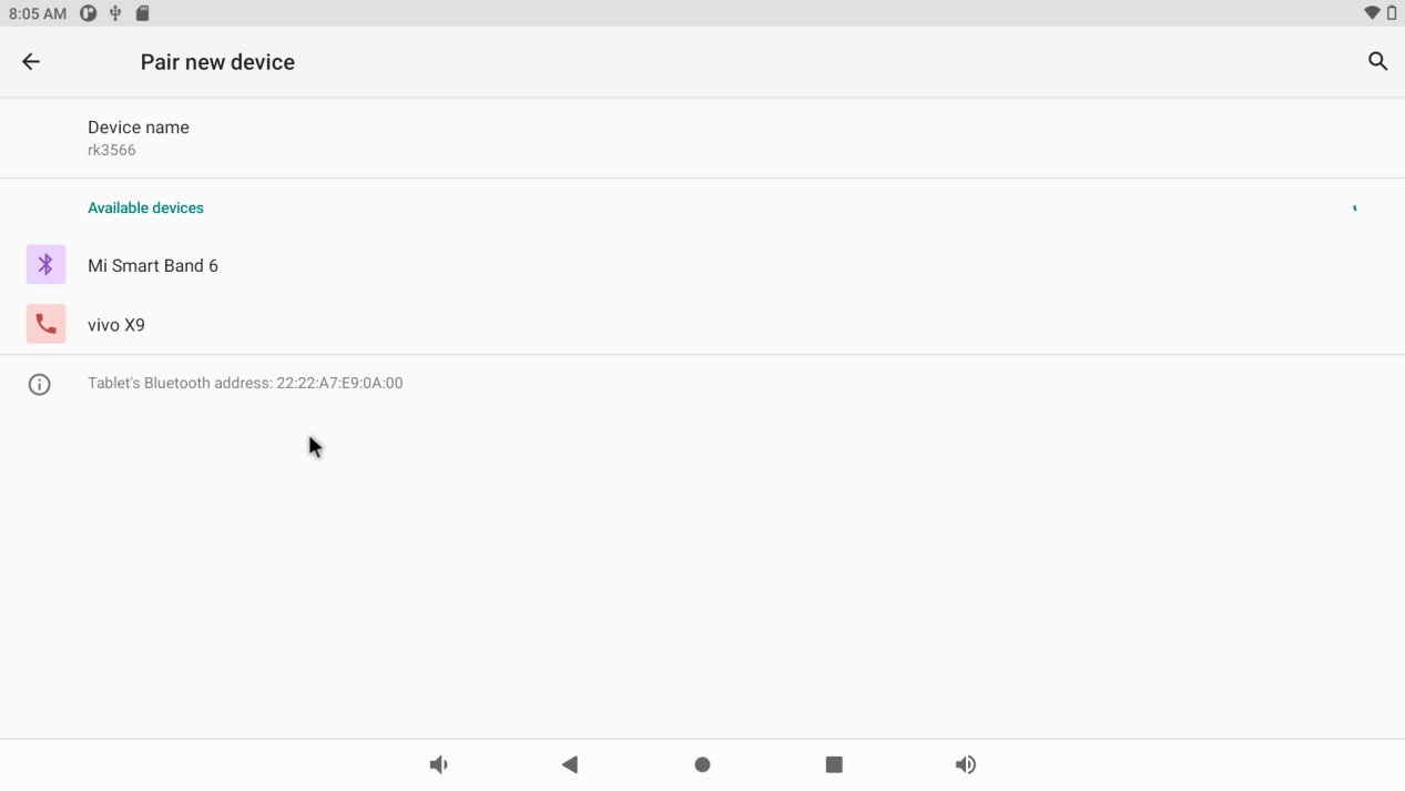
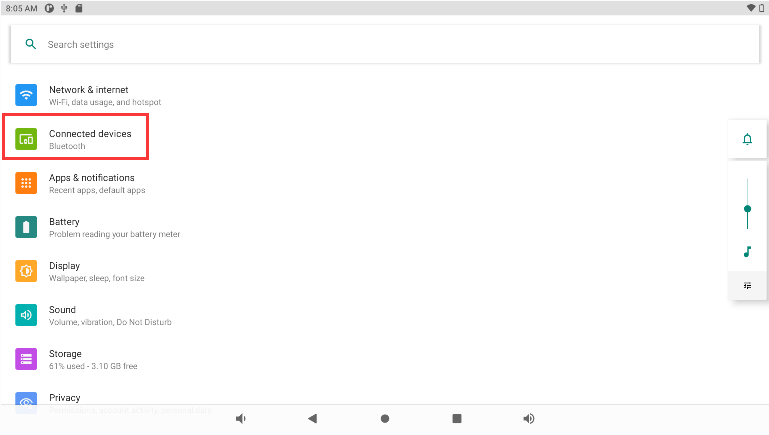
6.6.2 Bluetooth
Click Settings -> Connected devices -> Pair new device
Select the available device in the list to pair.
6.7 Ethernet
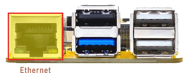
Ethernet
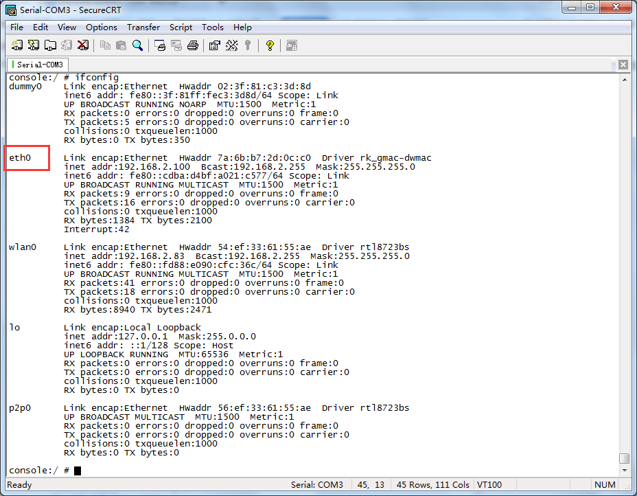
Connect the board and router with an Ethernet cable (default DHCP=Yes). User can ping URL/IP at terminal, or open the browser to test Network.
1ifconfig
2ping www.boardcon.com
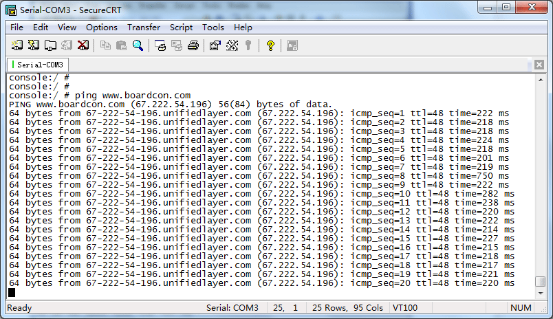
Ping IP
6.8 RTC
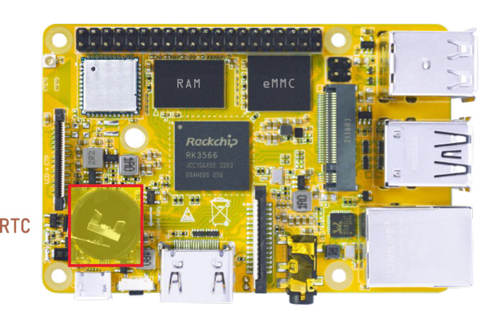
RTC
Insert a CR1220 battery before test. It keeps the time running when the main power is off.
1hwclock
 console:/ # hwclock
 2022-12-20 03:41:17+0000
 console:/ # hwclock
 2022-12-20 03:44:24+0000
 console:/ # hwclock
 2022-12-20 03:44:35+0000
 console:/ # hwclock
 2022-12-20 03:46:32+0000
6.9 ADB
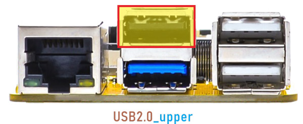
ADB
The default state of USB-AF is USB HOST after the development board runs normally. Execute the following commands in the terminal to switch ADB/Host.
1echo peripheral > /sys/devices/platform/fe8a0000.usb2-phy/otg_mode  //switch to ADB
2echo host > /sys/devices/platform/fe8a0000.usb2-phy/otg_mode        //switch to HOST
6.10 Expansion
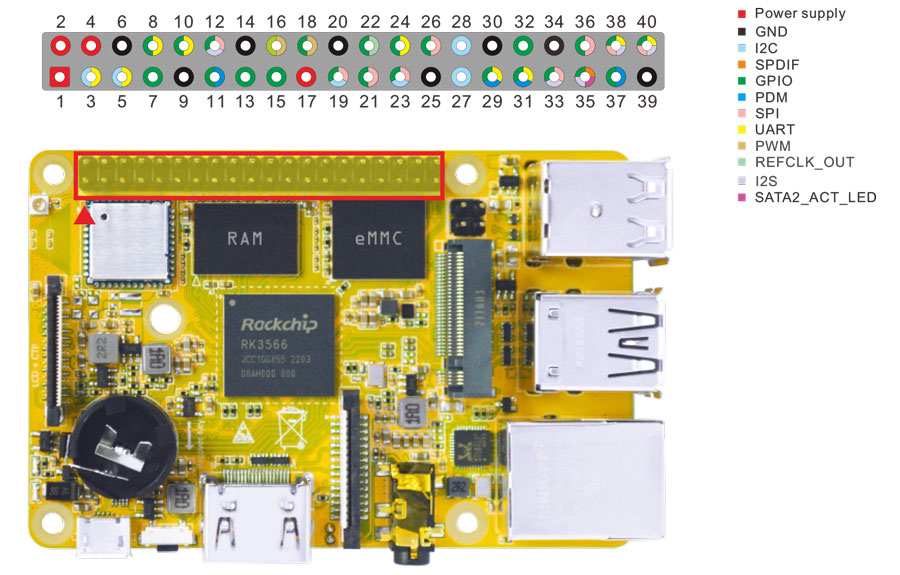
Expansion
6.10.1 UART
The UART loopback test is for reference only.
❶ push the file com to the Compact3566 via ADB.
1adb root
2adb remount
3adb push \xx\com /system  //\xx\ is the absolute path of 'com'
4chmod 777 /system/com    //modify com properties
❷ connect the transmit (TX) to the receive (RX) of UART.
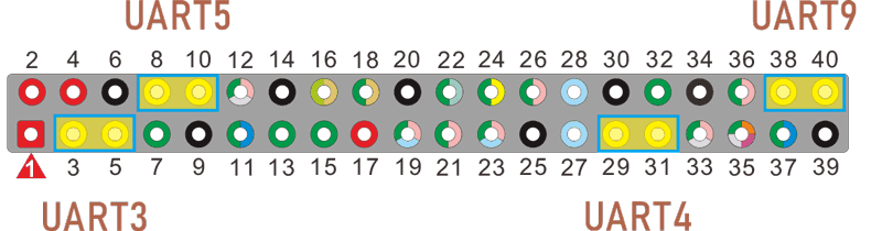
UART
UART3(ttyS3): Pin5(TX), Pin3(RX)
UART4(ttyS4): Pin29(TX), Pin31(RX)
UART5(ttyS5): Pin8(TX), Pin10(RX)
UART9(ttyS9): Pin40(TX), Pin38(RX)
❸ execute command, then input character to test UART.
1./system/com /dev/ttyS3 115200 8 0 1 //test UART3
130|console:/ # ./system/com /dev/ttyS3 115200 8 0 1
port = /dev/ttyS3
baudrate = 115200
cs = 8
parity = 0
stopb = 1
123456789
RECV: 123456789
ab9876543210
RECV: ab9876543210
❹ press Ctrl + C to exit UART3 testing, execute the command to test UART4.
1./system/com /dev/ttyS4 115200 8 0 1 //test UART4
130|console:/ # ./system/com /dev/ttyS4 115200 8 0 1
port = /dev/ttyS3
baudrate = 115200
cs = 8
parity = 0
stopb = 1
78787878
RECV: 78787878
rtrtrtrt
RECV: rtrtrtrt
The test methods for UART5(ttyS5) and UART9(ttyS9) are also similar.
6.10.2 SPI
❶ Push the file spidev_test to the Compact3566 with ADB.
1adb root
2adb remount
3adb push \xx\spidev_test /system  //\xx\ is the absolute path to store spidev_test
4adb shell
5chmod 777 /system/spidev_test   //modify spidev_test properties
❷ connect SPI0_MOSI_M0 and SPI0_MISO_M0 of SPI0.
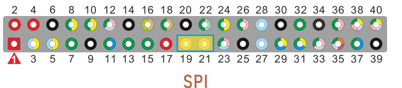
pin19: SPI0_MOSI_M0
pin21: SPI0_MISO_M0
❸ Execute the command to test SPI0.
1./system/spidev_test
 console:/ # ./system/spidev_test
 spi mode: 0
 bits per word: 8
 max speed: 500000 Hz (500 KHz)

 FF FF FF FF FF FF
 40 00 00 00 00 95
 FF FF FF FF FF FF
 FF FF FF FF FF FF
 FF FF FF FF FF FF
 DE AD BE EF BA AD
 F0 0D
 console:/ #
6.10.3 IR
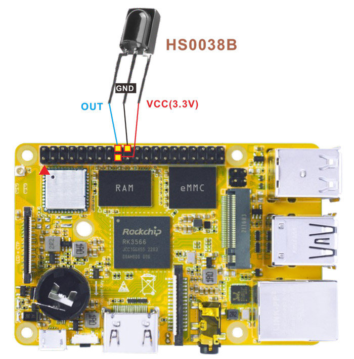
IR connection
❶ connect IR receiver and board.
OUT: connect to PWM3_IR (pin18)
GND: connect to Ground
VCC: connect to 3.3V
❷ execute the command.
1echo 1 > /sys/module/rockchip_pwm_remotectl/parameters/code_print
❸ operate the IR controller and view the received data.
 console:/ # echo 1 > /sys/module/rockchip_pwm_remotectl/parameters/code_print
 [ 102.405500] USERCODE=0xbf40
 [ 102.433396] RMC_GETDATA=b8
 [ 102.700999] USERCODE=0xbf40
 [ 102.729040] RMC_GETDATA=b9
 [ 102.814926] USERCODE=0xbf40
 [ 102.842869] RMC_GETDATA=e2
6.11 Camera
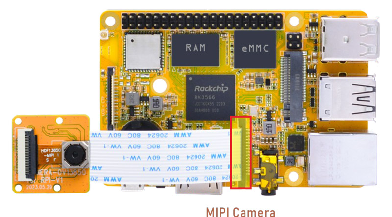
Camera
Connect the camera module (OV13850) to the development board before power on, then click the camera APP to test.