6. Buildroot Application
6.1 Display
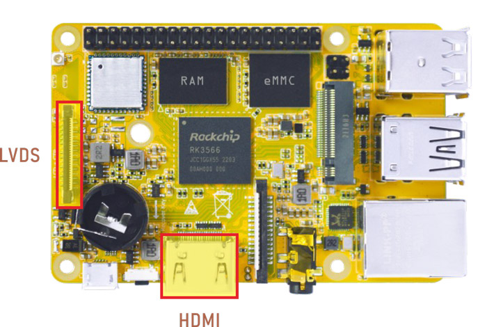
Display IO
Connect the board and monitor with a HDMI cable, then start up.
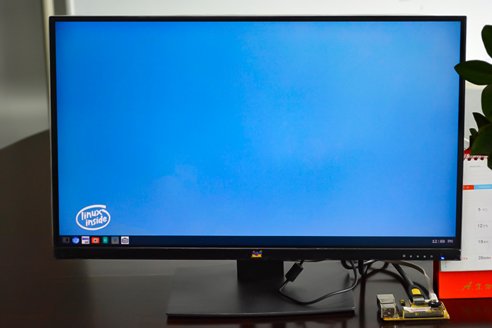
HDMI display
Note
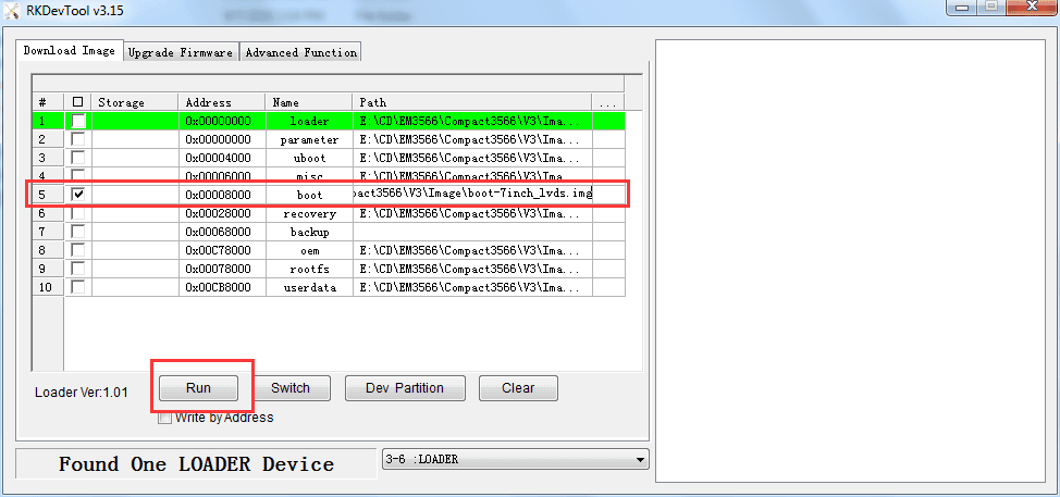
The Boardcon factory default HDMI display. If change to LVDS please reflash
boot.img.
10.1” LVDS LCD:
boot-10.1inch_lvds.img7” LVDS LCD:
boot-7inch_lvds.imgHDMI:
boot-hdmi.img
6.2 Audio IO
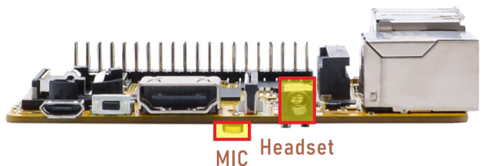
aplay -l                            //list available sound cards
arecord -D hw:1,0 -f cd test.wav    //recording. priority: headset > MIC
aplay -D plughw:0,0 test.wav        //play record file via HDMI
aplay -D plughw:1,0 test.wav        //play record file via headset
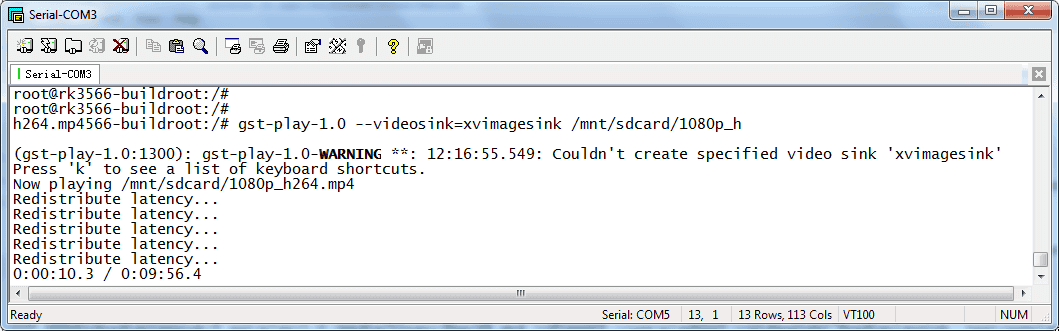
6.3 Video Player
Copy video file to SD card or U-disk then insert it to the board.
1gst-play-1.0 --videosink=xvimagesink XXX //`XXX` is file path
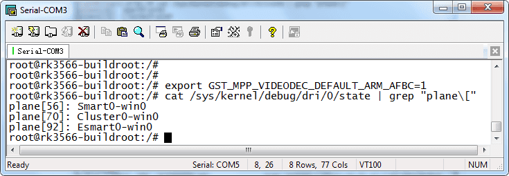
1export GST_MPP_VIDEODEC_DEFAULT_ARM_AFBC=1 //set AFBC
2cat /sys/kernel/debug/dri/0/state | grep "plane\[" //view the plane id (select Cluster0-win0)
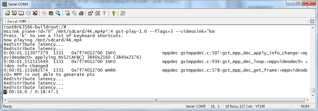
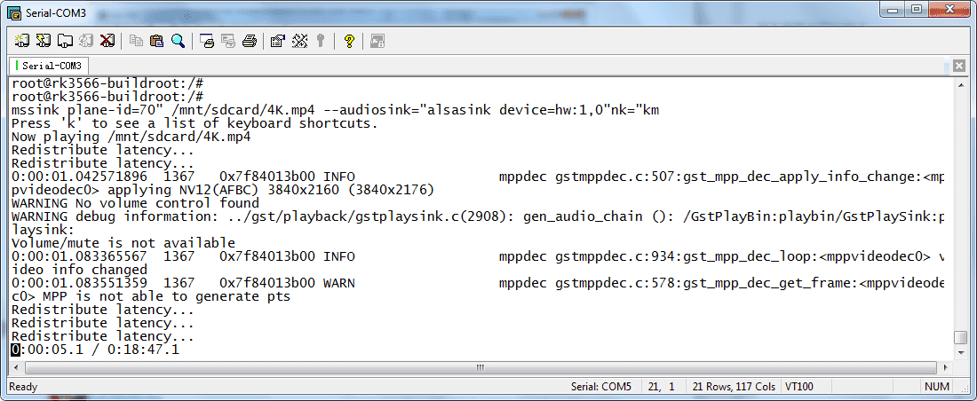
3GST_DEBUG=*mpp*:4 gst-play-1.0 --flags=3 --videosink="kmssink plane-id=70" /XXX //play video(`XXX` is the file path)
4GST_DEBUG=*mpp*:4 gst-play-1.0 --flags=3 --videosink="kmssink plane-id=70" /mnt/sdcard/4K.mp4 --audiosink="alsasink device=hw:1,0" //specify audio channel output
6.4 SD Card
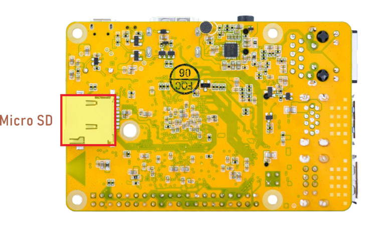
Micro SD
The SD card is automatically mounted. Compact3566 supports SD Hot-plug.
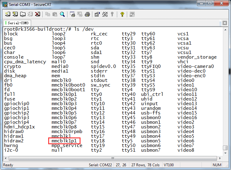
1ls /dev
2df -h
3ls /mnt/sdcard
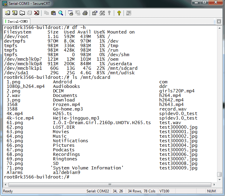
View SD contents
6.5 USB Host
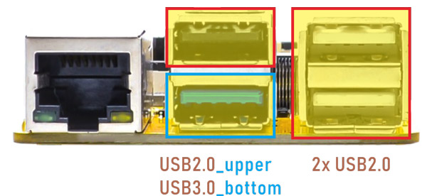
Compact3566 features 1x USB3.0 and 3x USB2.0 Host(USB OTG can be used for Host).
1ls /dev
2df -h
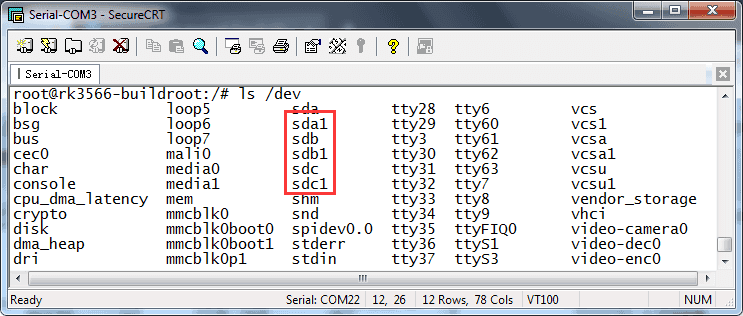
list devices
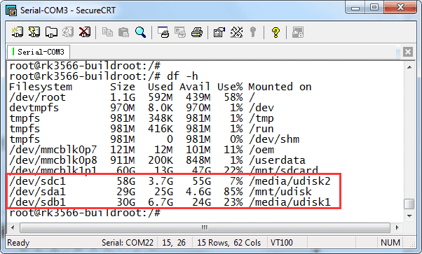
Mounted USB device
The USB3.0 default support Superspeed.
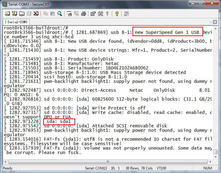
USB3.0 Superspeed
6.6 M.2 SSD
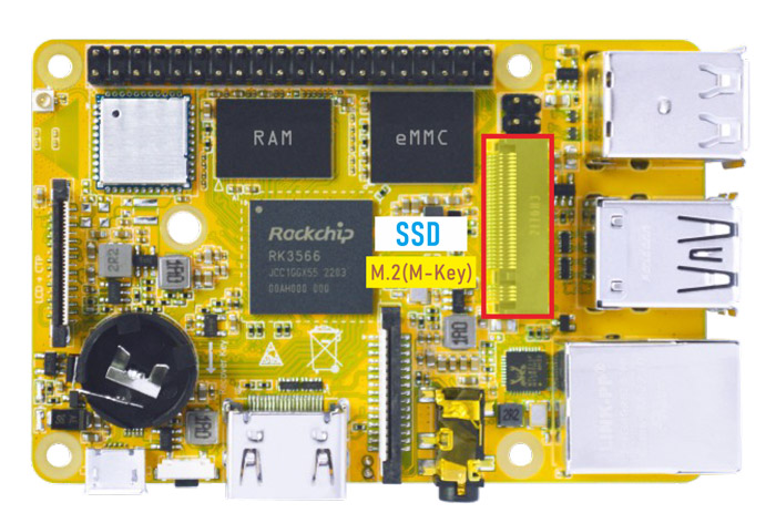
M.2 SSD
❶ format SSD to ext4 file system on Ubuntu system first.
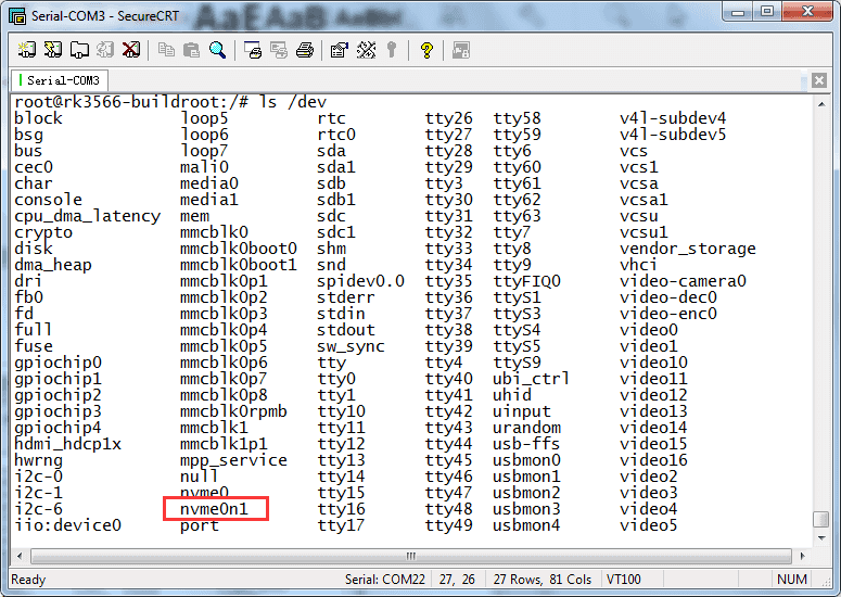
1ls /dev                              //view the SSD device name
2mke2fs -t ext4 /dev/block/nvme0n1    //format ssd to ext4
❷ mount SSD.
1mkdir /mnt/ssd
2mount -t ext4 /dev/nvme0n1 /mnt/ssd
3ls /mnt/ssd
6.7 WiFi & Bluehost
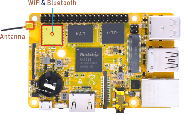
WiFi & Bluehost
6.7.1 WiFi
❶ connect the WiFi antenna.
❷ search for wireless hotspots and config.
1iwlist wlan0 scan                     //search hotspot
2vi /data/cfg/wpa_supplicant.conf      //configure hotspot. Input user SSID and password
#Input SSID and password
ctrl_interface=/var/run/wpa_supplicant
ap_scan=1
update_config=1

network={
        ssid="input your SSID here"
        psk="input password here"
        key_mgmt=WPA-PSK
}
~
❸ restart wifi and connect to the hotspot.
1ifconfig wlan0 down
2killall wpa_supplicant
3ifconfig wlan0 up
4wpa_supplicant -B -i wlan0 -c /data/cfg/wpa_supplicant.conf   //connect to the hotspot
❹ view the network status and ping URL/IP to test.
1ifconfig              //view the network status
2ping -I wlan0 www.boardcon.com    //ping URL to test network
6.7.2 Bluetooth
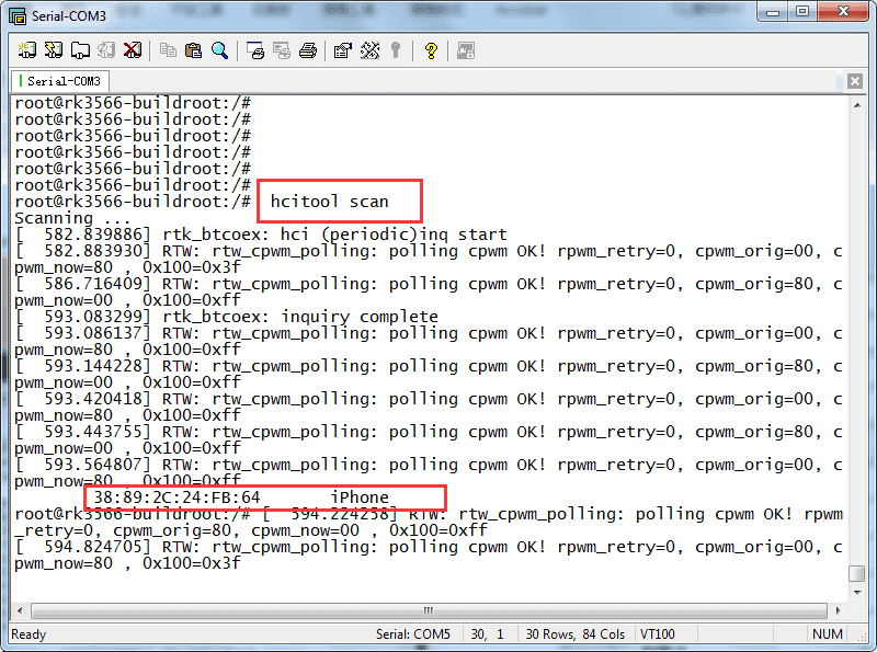
❶ open Bluetooth and scan nearby devices.
1hciconfig hci0 up
2hciconfig -a                //view device status
3hciconfig hci0 iscan        //allow Bluetooth to be searched
4hcitool scan
❷ allow Bluetooth to be pairable.
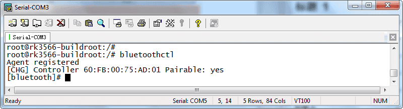
1bluetoothctl
❸ click BlueZ 5.62 (Compact3566 Bluetooth) in phone to pair. Input yes.
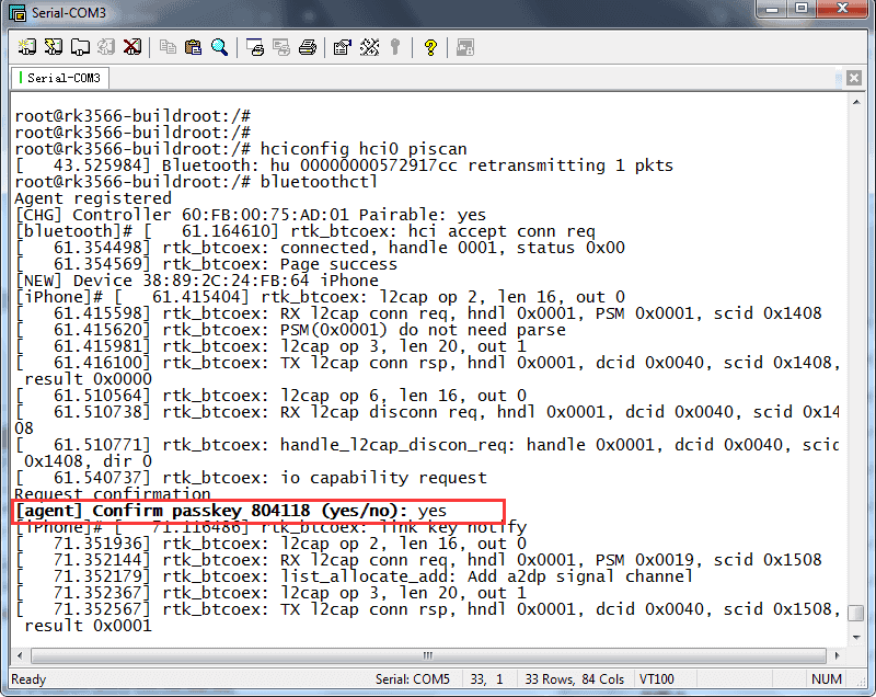
❹ connect and trust Bluetooth
1connect 38:89:2C:24:FB:64     //connect bluetooth
2trust 38:89:2C:24:FB:64       //trust bluetooth

Connect & trust Bluetooth
6.8 Ethernet
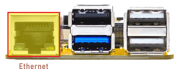
Ethernet
Connect the Board and router with an Ethernet cable (default DHCP=Yes). Ping URL/IP at terminal to test.
eg.
1ifconfig
2ping www.boardcon.com
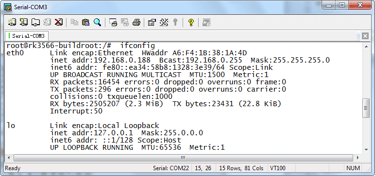
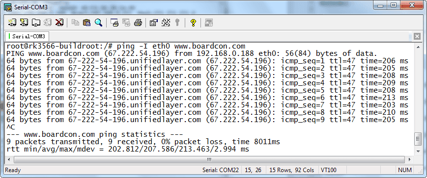
Ping URL
6.9 RTC
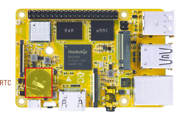
RTC
❶ insert a CR1220 battery before test. It keeps the time running when the main power is off.
❷ execute the follow command to set the RTC time.
1date -s "2023-09-08 12:00:00"     //set system time
2hwclock -w           //synchronize system time and RTC time
3hwclock
root@rk3566-buildroot:/ # date -s "2023-09-08 12:00:00"
Fri Sep  8 12:00:00 UTC 2023
root@rk3566-buildroot:/ # hwclock -w
root@rk3566-buildroot:/ # hwclock
Fri Sep  8 12:00:23 2023  0.000000 seconds
root@rk3566-buildroot:/ # hwclock
Fri Sep  8 12:00:24 2023  0.000000 seconds
root@rk3566-buildroot:/ # hwclock
Fri Sep  8 12:00:25 2023  0.000000 seconds
6.10 Expansion
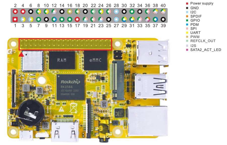
Expansion
6.10.1 UART
The UART loopback test is for reference only.
❶ copy com to SD card and then insert it to the card slot.
❷ copy com from SD card to the board.
1cp /mnt/sdcard/com /system
❸ connect the transmit (TX) pin to the receive (RX) pin of UART. After executes the command, input character to test UART.
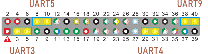
UART
UART3(ttyS3): Pin5(TX), Pin3(RX)
UART4(ttyS4): Pin29(TX), Pin31(RX)
UART5(ttyS5): Pin8(TX), Pin10(RX)
UART9(ttyS9): Pin40(TX), Pin38(RX)
1./system/com /dev/ttyS3 115200 8 0 1 //Test UART3
root@rk3566-buildroot:/ # ./system/com /dev/ttyS3 115200 8 0 1
port = /dev/ttyS3
baudrate = 115200
cs = 8
parity = 0
stopb = 1
1234567890
RECV: 1234567890
AB9876543210
RECV: AB9876543210
❹ press Ctrl + C to exit UART3 testing, execute the command to test UART4.
1 ./system/com /dev/ttyS4 115200 8 0 1 //Test UART4
root@rk3566-buildroot:/ # ./system/com /dev/ttyS4 115200 8 0 1
port = /dev/ttyS4
baudrate = 115200
cs = 8
parity = 0
stopb = 1
12345678asdf
RECV: 12345678asdf
asdfgh1234000
RECV: asdfgh1234000
The method for testing UART5(ttyS5) and UART9(ttyS9) is similar.
6.10.2 SPI
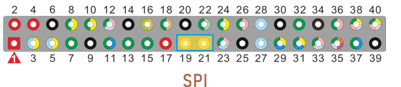
pin19: SPI0_MOSI_M0
pin21: SPI0_MISO_M0
Execute the command after short-circuit SPI0_MOSI_M0 and SPI0_MISO_M0 of SPI0, you can see the change of SPI0 data.
1spidev0.0_test
 root@rk3566-buildroot:/ # spidev0.0_test
 spi mode: 0
 bits per word: 8
 max speed: 500000 Hz (500 KHz)

 FF FF FF FF FF FF
 40 00 00 00 00 95
 FF FF FF FF FF FF
 FF FF FF FF FF FF
 FF FF FF FF FF FF
 DE AD BE EF BA AD
 F0 0D
 root@rk3566-buildroot:/ #
6.10.3 IR
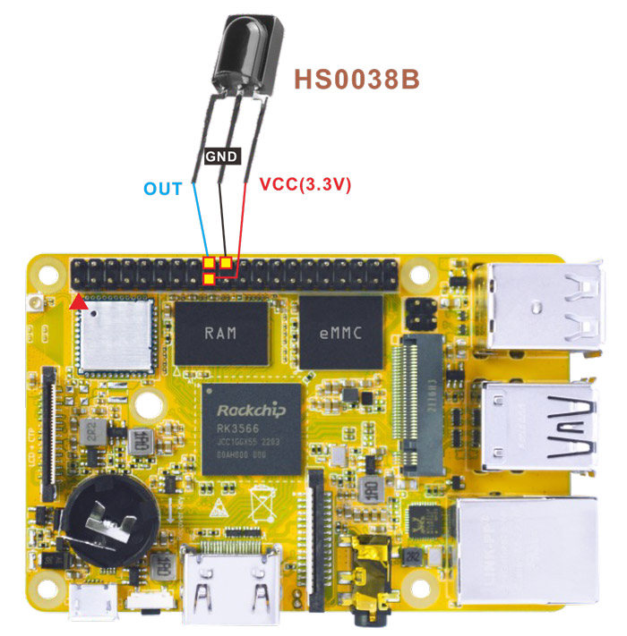
IR connection
❶ connect IR receiver and board.
OUT: connect to PWM3_IR (pin18)
GND: connect to Ground
VCC: connect to 3.3V
❷ execute the command:
1echo 1 > /sys/module/rockchip_pwm_remotectl/parameters/code_print //obtain the data
❸ operate the IR controller and view the received data.
 root@rk3566-buildroot:/# echo 1 > /sys/module/rockchip_pwm_remotectl/parameters/code_print
 [ 6494.220456] USERCODE=0xfe01
 [ 6494.472521] RMC_GETDATA=b8
 [ 6494.499518] USERCODE=0xfe01
 [ 6494.685072] RMC_GETDATA=b8
6.11 Camera
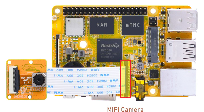
Camera
❶ Connect the camera module (OV13850) to the development board before power on.
❷ check device number
1grep ov13850 /sys/class/video4linux/v*/name
2grep "" /sys/class/video4linux/v*/name | grep mainpath
❸ preview/ record/ take a picture
1gst-launch-1.0 v4l2src device=/dev/video8 ! video/x-raw,format=NV16,width=1280,height=800, framerate=30/1 ! kmssink //preview
2gst-launch-1.0 v4l2src device=/dev/video8 num-buffers=100 ! video/x-raw,format=NV12,width=1920,height=1088,framerate=30/1 ! videoconvert ! mpph264enc ! h264parse ! mp4mux ! filesink location=/tmp/h264.mp4 //video recording
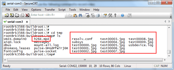
3gst-launch-1.0 -v v4l2src device=/dev/video8 num-buffers=10 ! video/x-raw,format=NV12,width=1280,height=800 ! mppjpegenc ! multifilesink location=/tmp/test%05d.jpg //take a picture
Files storage path is /tmp