6. Android Application
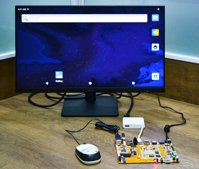
6.1 Display
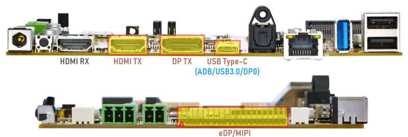
Idea3588 supports DP, HDMI and LCD(eDP) display sync.
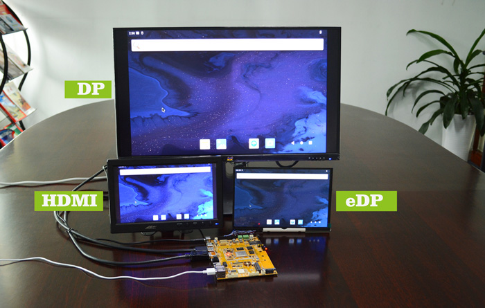
HDMI display
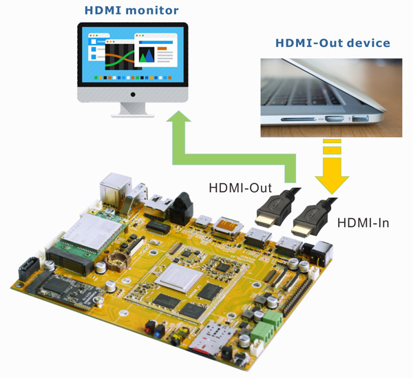
6.2 HDMI IN
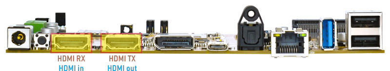
❶ Connect the HDMI_OUT on the output device to the HDMI_IN on the Idea3588, HDMI_OUT on the Idea3588 to the HDMI monitor, then power on.
❷ Open HdmiIn
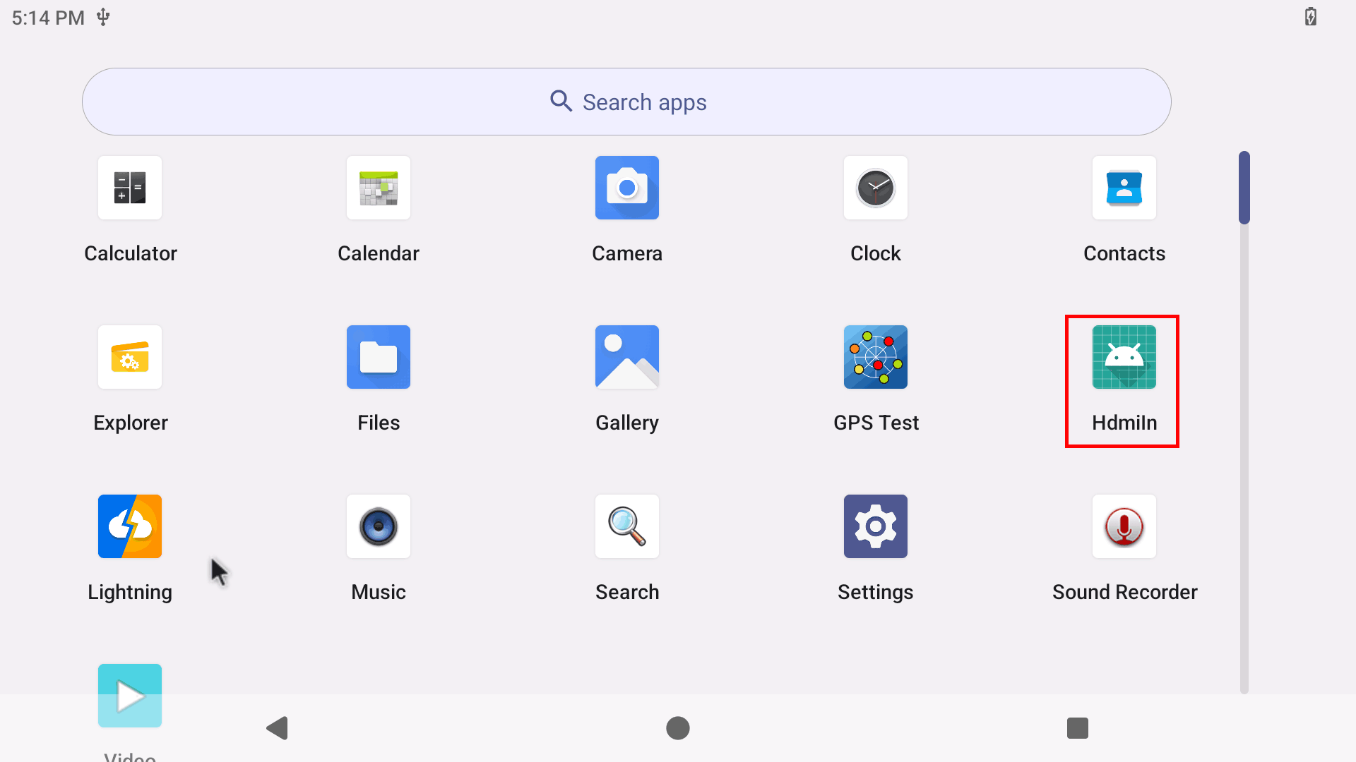
HDMI IN
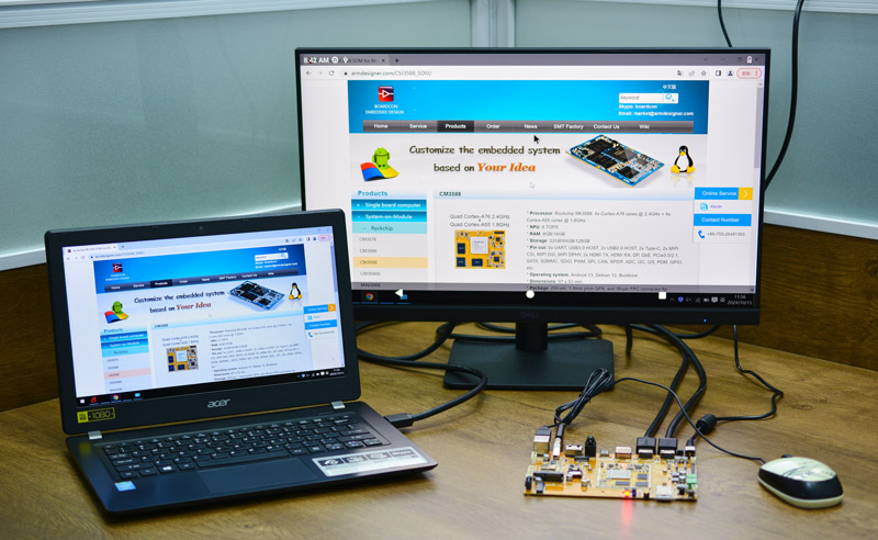
❸ Swipe up and click ⚪(Home) to exit HDMI IN.
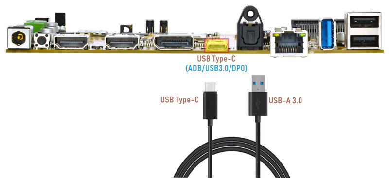
6.3 USB Type-C
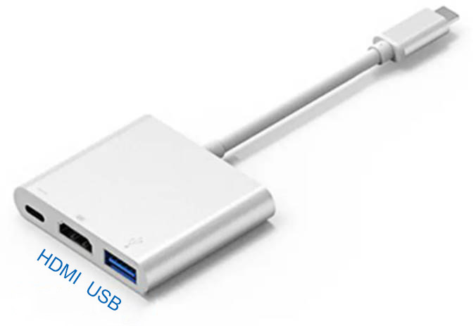
Docking station
Features Supported by the Type-C Interface:
Reversible Design: Allows insertion in either orientation for user convenience.
Data Transmission Roles: Supports flexible designation of host and device roles.
Multiple Protocol Support: Compatible with USB 3.0 and DisplayPort, enabling high-speed data transmission.
6.3.1 ADB
ADB is the command-line debugging tool for debian, and it can use for system logs, uploading and downloading the files, installing the applications, etc.
❶ Connect the board and PC host with Type-C cable.
❷ Install ADB driver on Windows system.
❸ Press Windows + R to open the Run program. Type cmd and press Enter.
❹ Execute the follow commands to enable ADB.
adb root
adb remount
adb shell
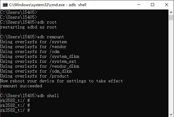
enable ADB
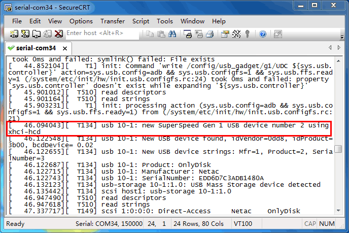
6.3.2 Type-C to USB3.0
Idea3588 supports Type-C to USB3.0. The USB device can be used directly without install any driver.
6.3.3 DP Alt Mode
DisplayPort Alternate Mode (DP Alt Mode) is a technology that facilitates the transmission of DisplayPort video signals through a USB Type-C interface. It enables devices to output video and audio via a USB-C connection without requiring a dedicated DisplayPort connector. This allows users to connect a display using a single USB-C port while transmitting video, audio, and additional data.
Boardcon has conducted the testing at Type-C to HDMI/DP (3840x2160 @ 60Hz).
Type-C to HDMI
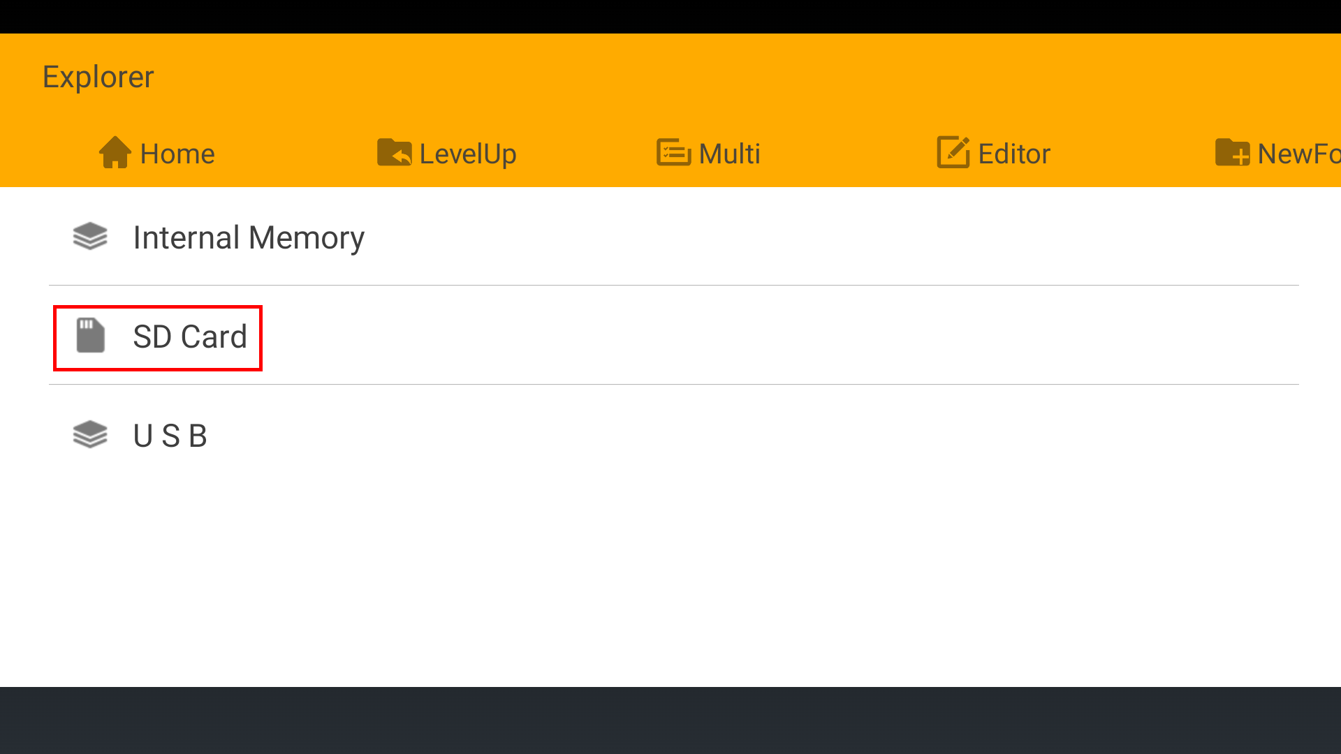
6.4 SD Card
Idea3588 supports SD Hot-plug.
6.5 USB Host
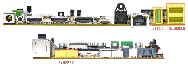
The USB Host can be used to connect USB mouse, USB keyboard, U-Disk or other USB devices. The USB3.0 default supports Superspeed.
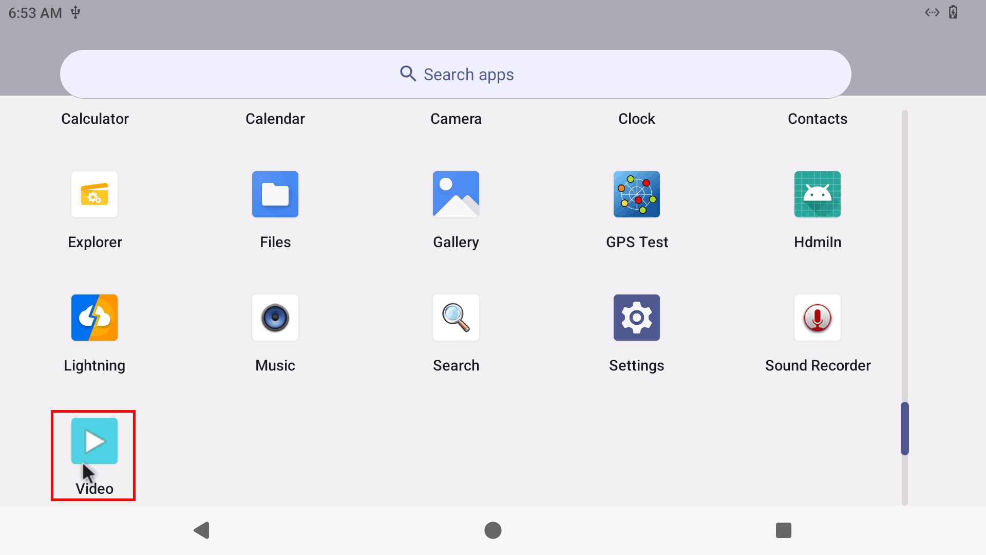
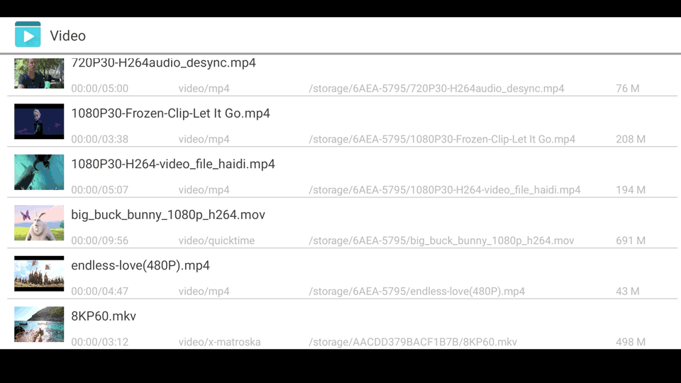
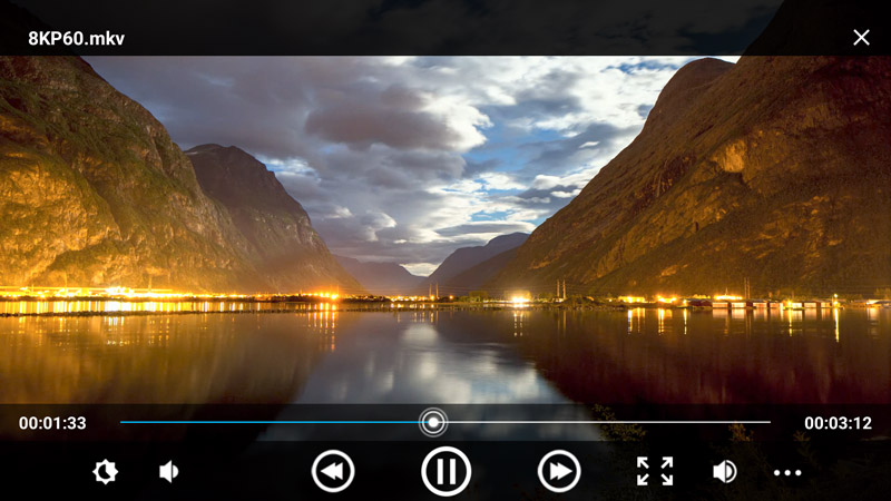
6.6 Video&Audio Player
Copy video file to SD_card/U-disk then insert it to the board. Click video file to play.
6.7 Ethernet
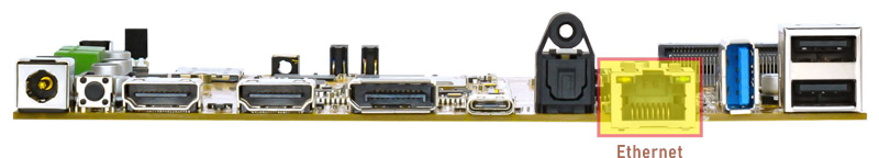
Connect the board and router with an Ethernet cable (default DHCP=Yes).
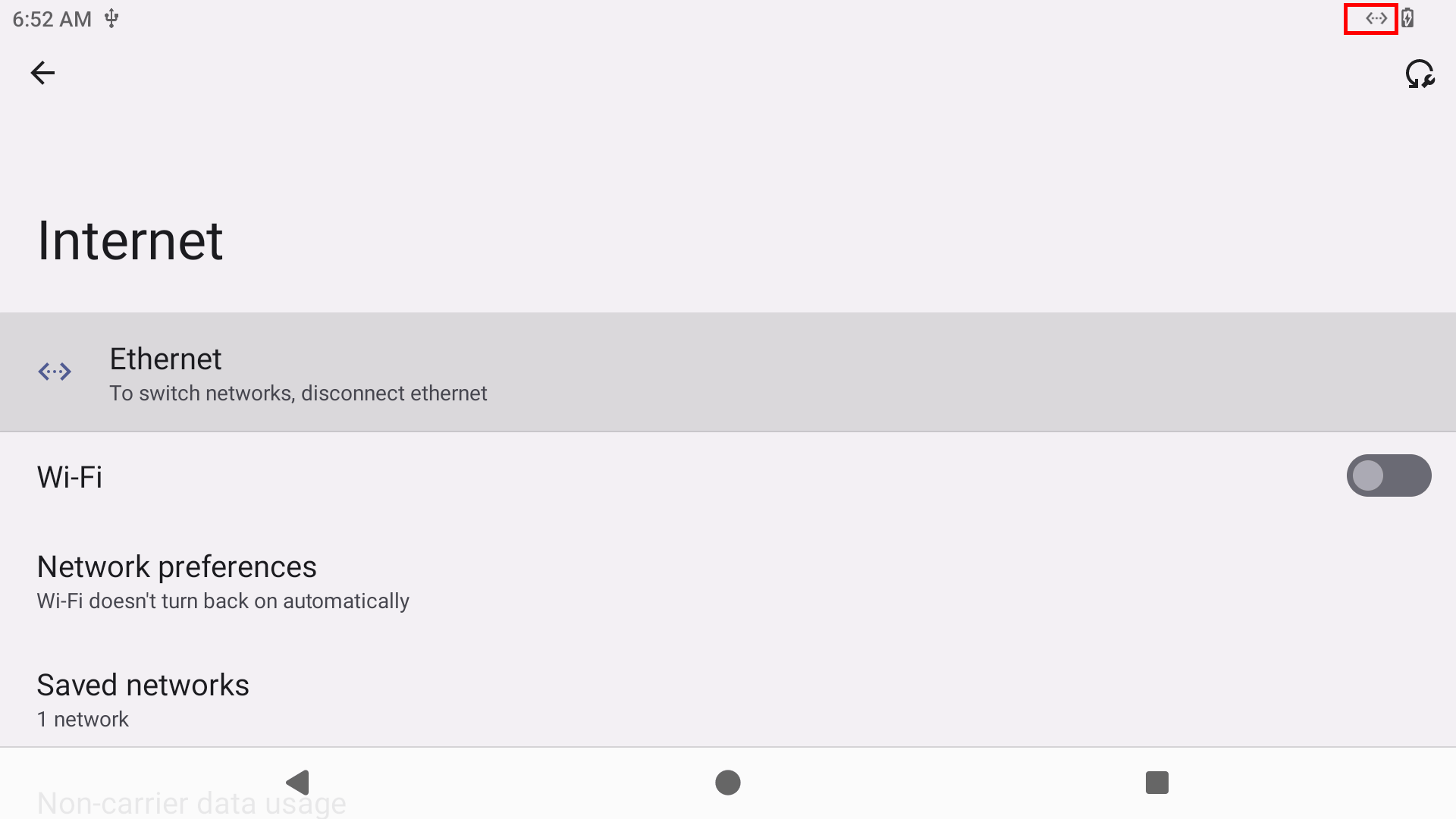
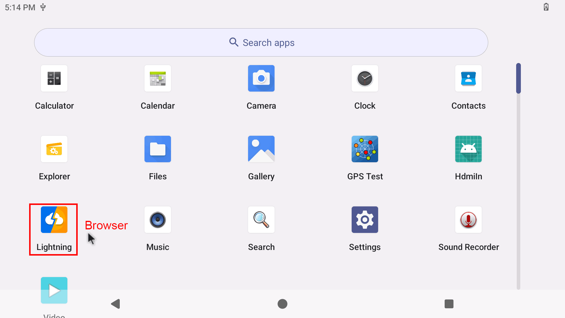
User can ping URL/IP at terminal, or open Lighting (browser) to test Network.
ifconfig                //Check the status of network interfaces
ping www.boardcon.com   //ping URL
6.8 Record
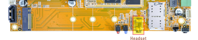
❶ Plug the Microphone into the 3.5mm Audio jack.
❷ Open Sound Recorder.
❸ Click Start to start recording.
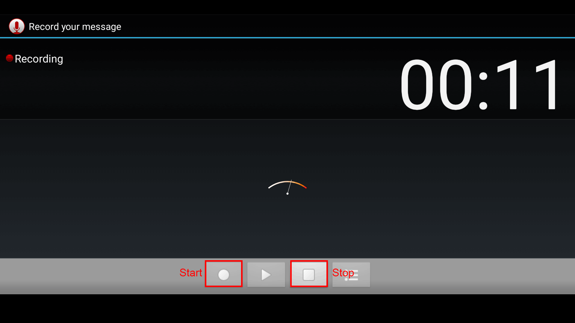
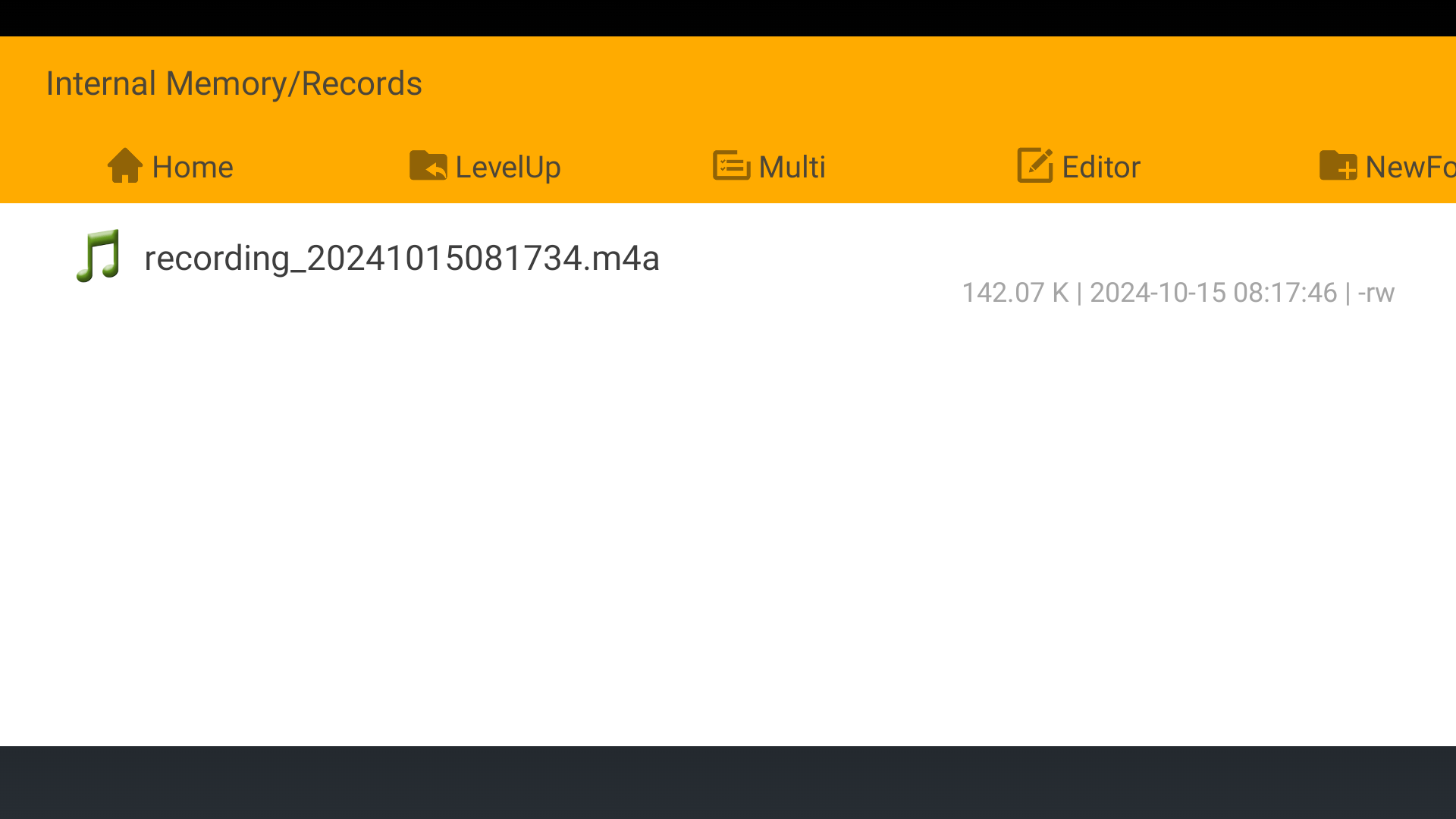
❹ After finish recording, click Stop and Save to store file.
The default storage path is Internal Memory/Records
6.9 RTC
Execute the command hwclock at CRT terminal
date -s "2024-10-14 12:00:00"     //set system date
hwclock -w                        //set the hardware clock to current system time
hwclock
Wait a moment, run hwclock again, it can be seen the time has changed.
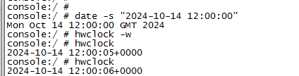
RTC battery keeps the time running when the main power is off.
6.10 WiFi & Bluetooth
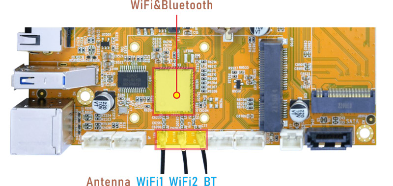
WiFi&BT module
6.10.1 WiFi
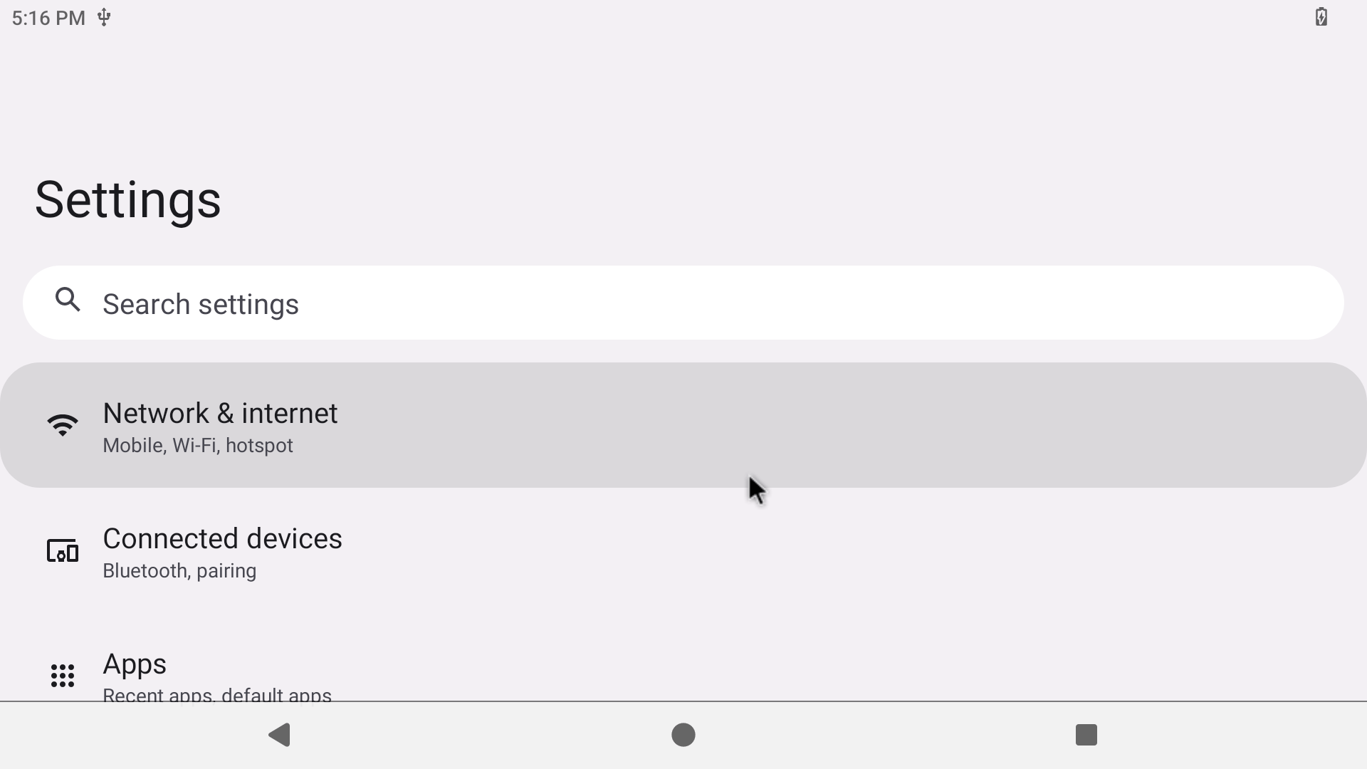
Connect the WiFi antenna, then click Settings -> Network & internet -> Wi-Fi -> turn on, select the SSID from the list of available networks and enter the password.
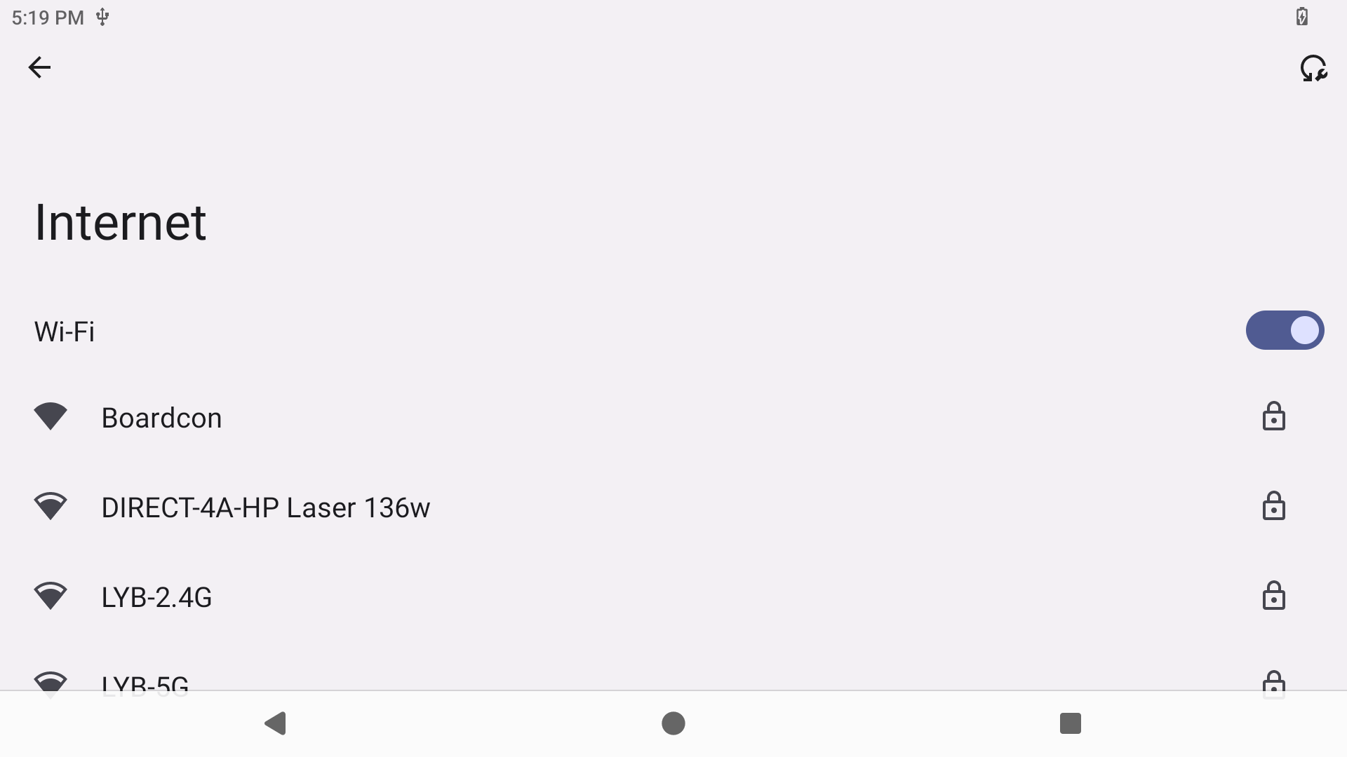
After connected, user can ping URL/IP at terminal, or open the browser to test Network.
6.10.2 Bluetooth
Click Settings -> Connected devices -> Pair new device
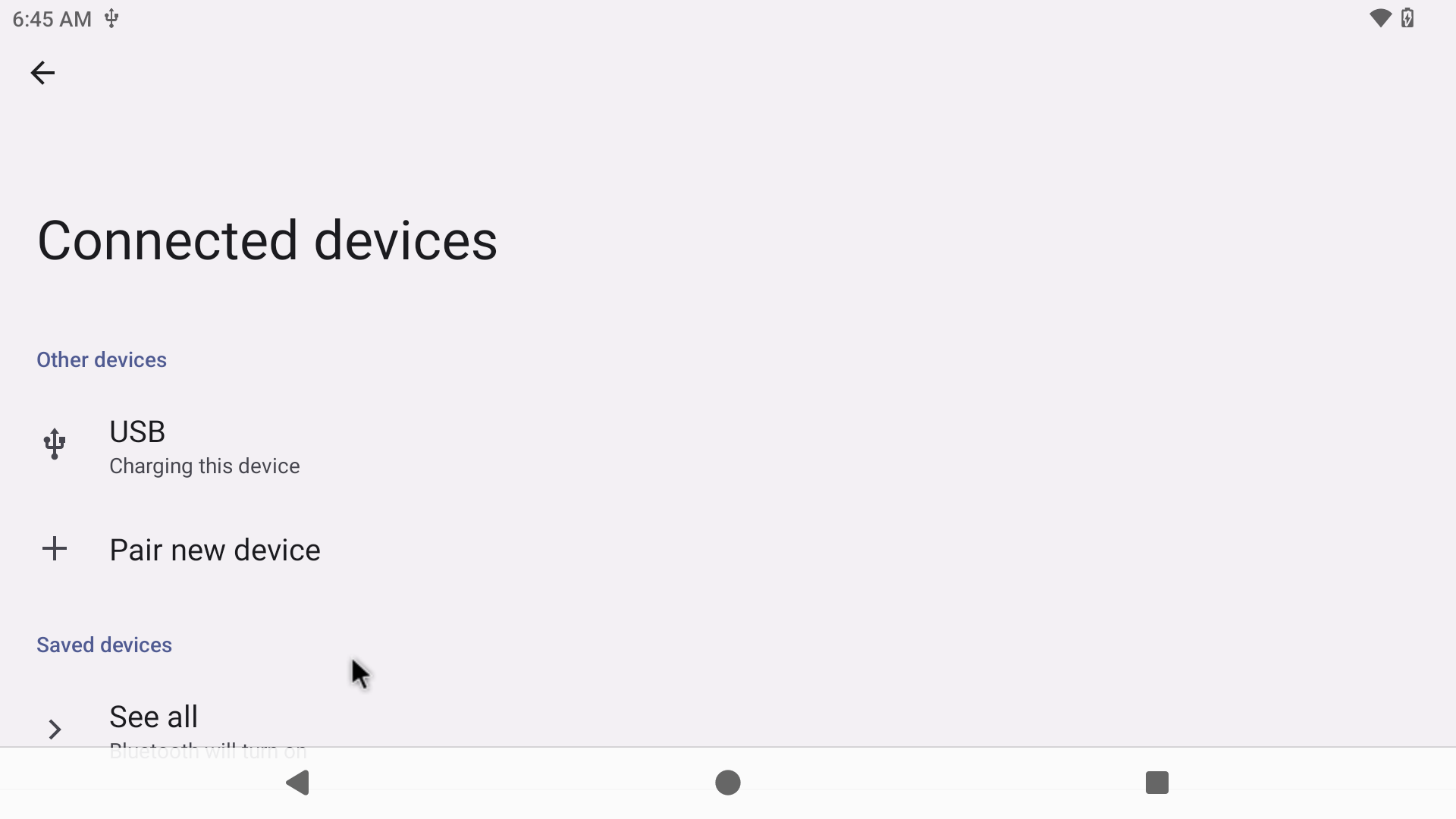
Select the available device in the list to pair.
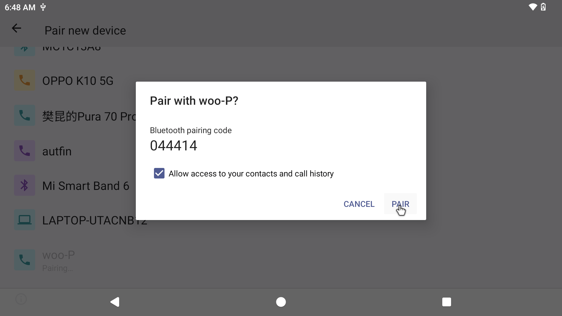
After pairing, devices can connect with each other automatically.
6.11 Camera
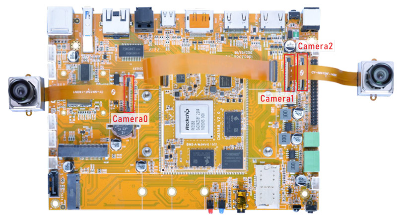
Connect the camera module (DC-IM415-1214V1) to the development board before power on, then click the camera APP to test.
Since camera0 and camera2 share the signal I2C2, they cannot be used simultaneously.
Boardcon Android13 firmware supports Camera0 to work alone, or camera1+camera2 (the camera in the combination can work independently)
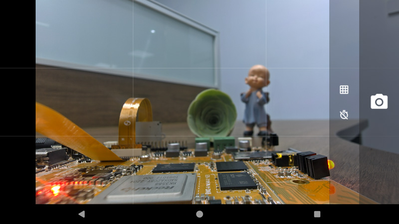
Camera preview
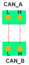
6.12 CAN
Connect CAN ports of Board A and Board B with the test line.
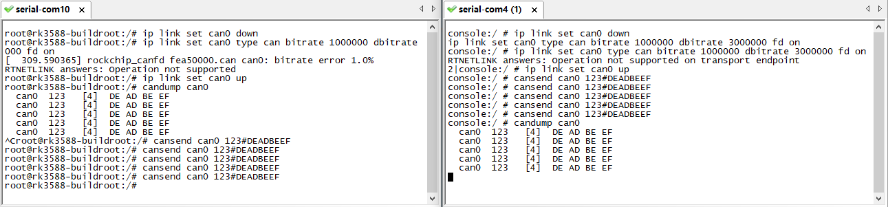
For Board A, execute the follow commands at Serial terminal A to set CAN_A as Receiver.
ip link set can0 down
ip link set can0 type can bitrate 1000000 dbitrate 3000000 fd on
ip link set can0 up
candump can0                  //set CAN0 as receive
For Board B, execute the follow commands at Serial terminal B to set CAN_B as Transmitter.
ip link set can0 down
ip link set can0 type can bitrate 1000000 dbitrate 3000000 fd on
ip link set can0 up
cansend can0 123#DEADBEEF      //CAN0 send characters 0xDE 0xAD 0xBE 0xEF
The Transmitter and receiver can be converted by execute the command
candump can0 //Receiver
or
cansend can0 123#DEADBEEF //Transmitter
6.13 RS485
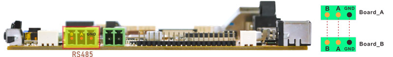
❶ Connect the RS485 ports of Board A and B with the test line.
❷ Execute command on the terminal serial ports of board A and board B respectively.
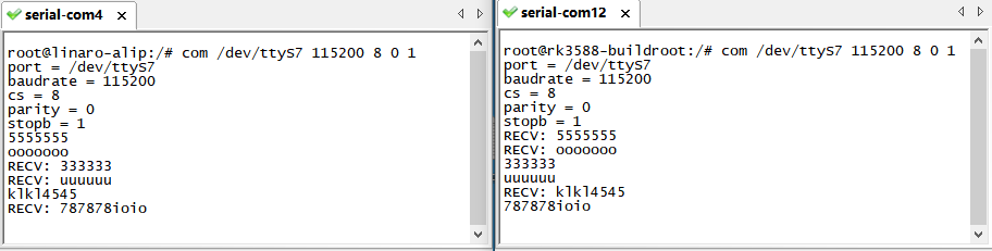
com /dev/ttyS7 115200 8 0 1
❸ Input character to test RS485 communication.
6.14 UART
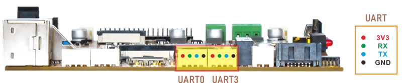
❶ Connect RX and TX of UART.
❷ Execute command.
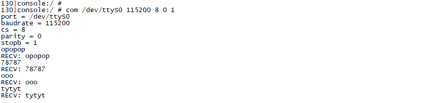
com /dev/ttyS0 115200 8 0 1 //UART0
❸ Input character to test.
com /dev/ttyS3 115200 8 0 1 //UART3
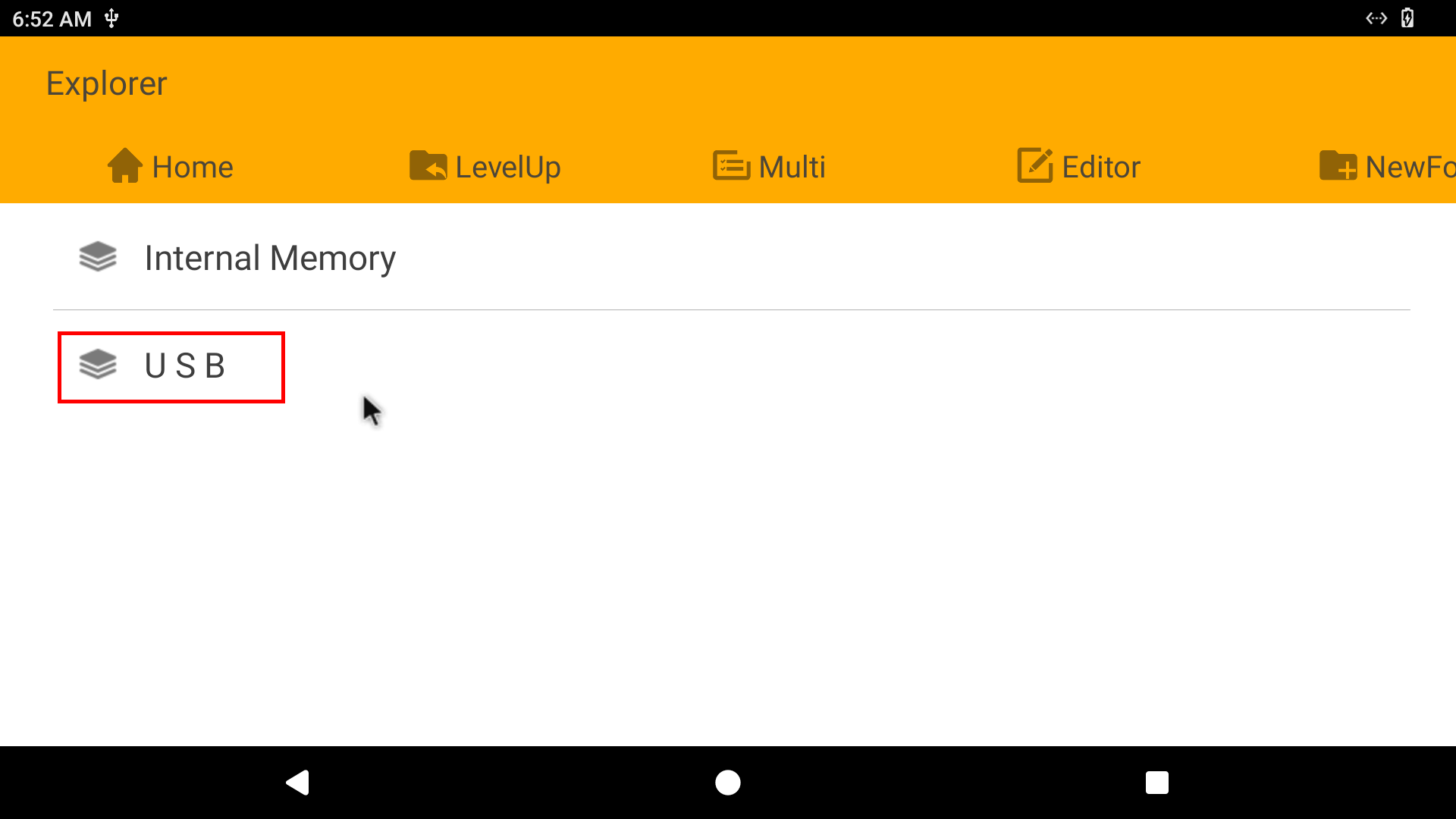
6.15 SATA
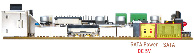
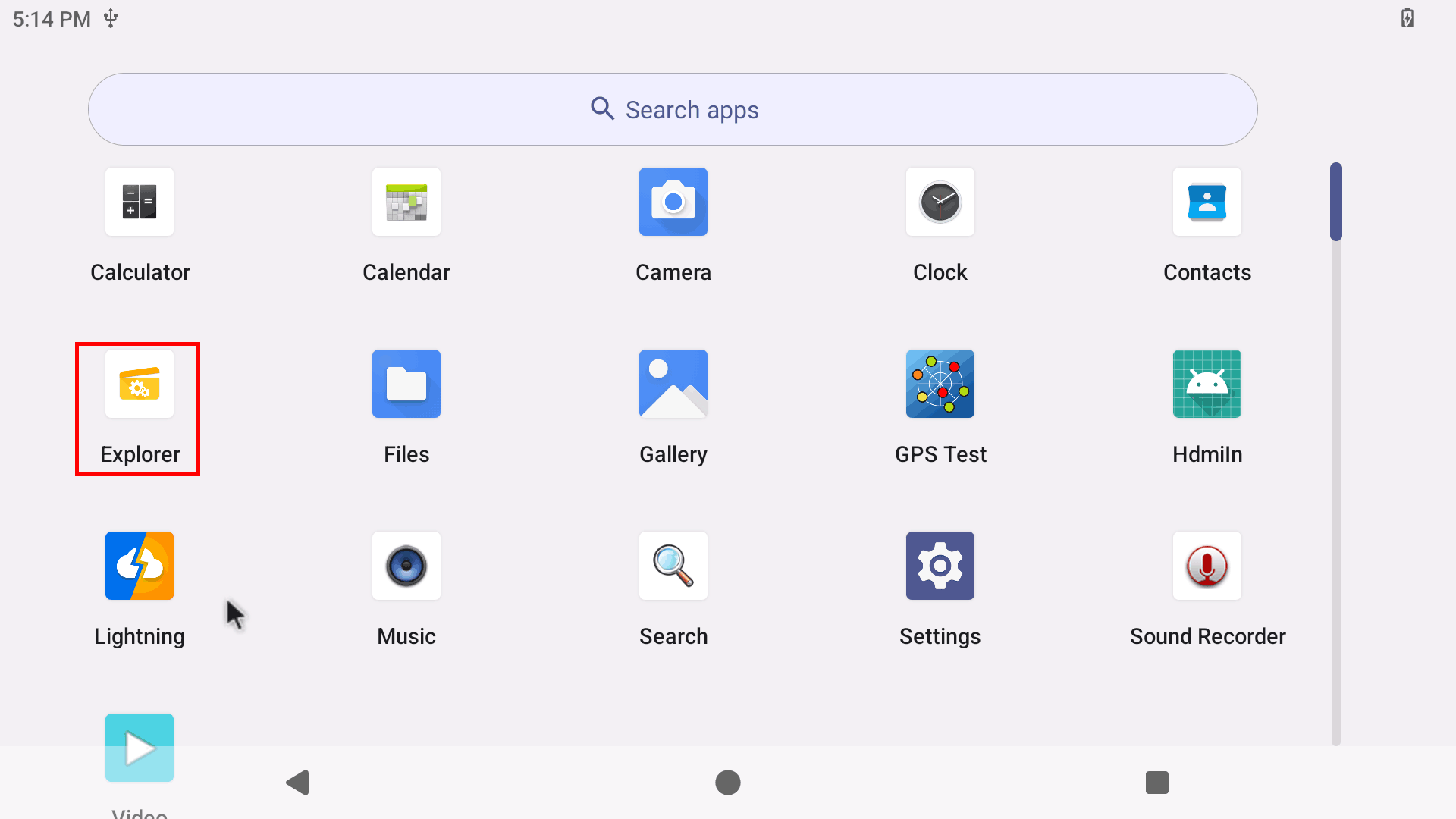
Connect SATA and SATA power to the board. Click Explorer to view the device.
6.16 M.2 NVME SSD
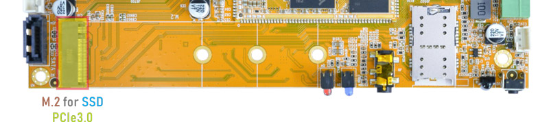
Connect SSD to the development board before power on. Click Explorer to view the device.
6.17 4G & GPS
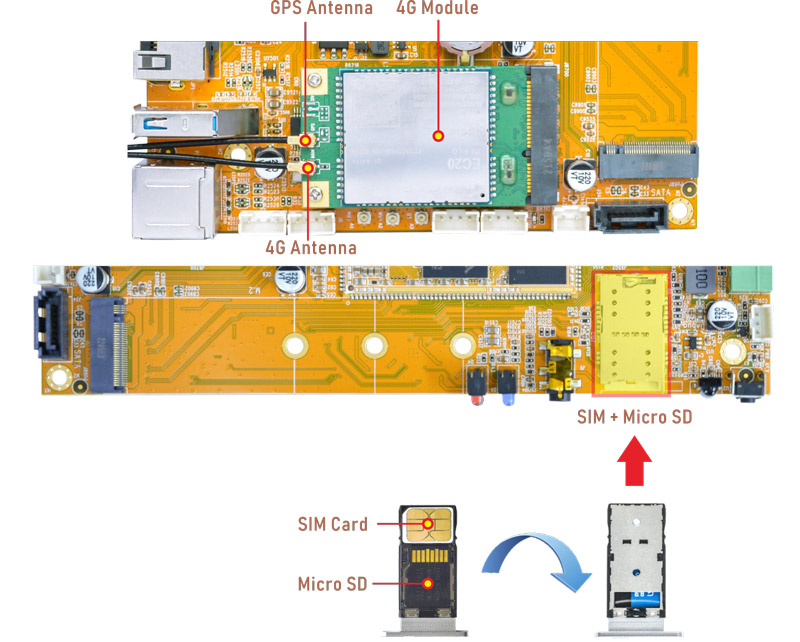
6.17.1 4G
❶ Insert 4G module to PCIe socket (4G model: EC20).
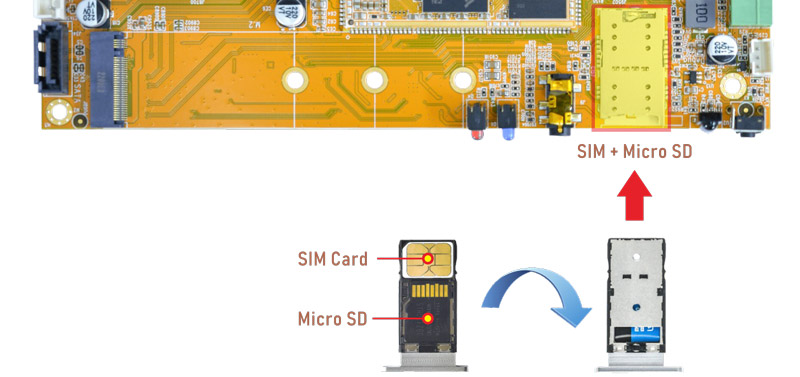
❷ Connect antenna and insert SIM card.
❸ Power on. The default connection is 4G network.
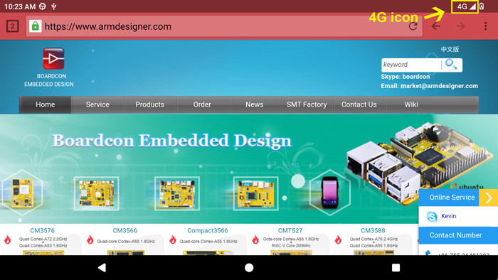
Browse the web using 4G network
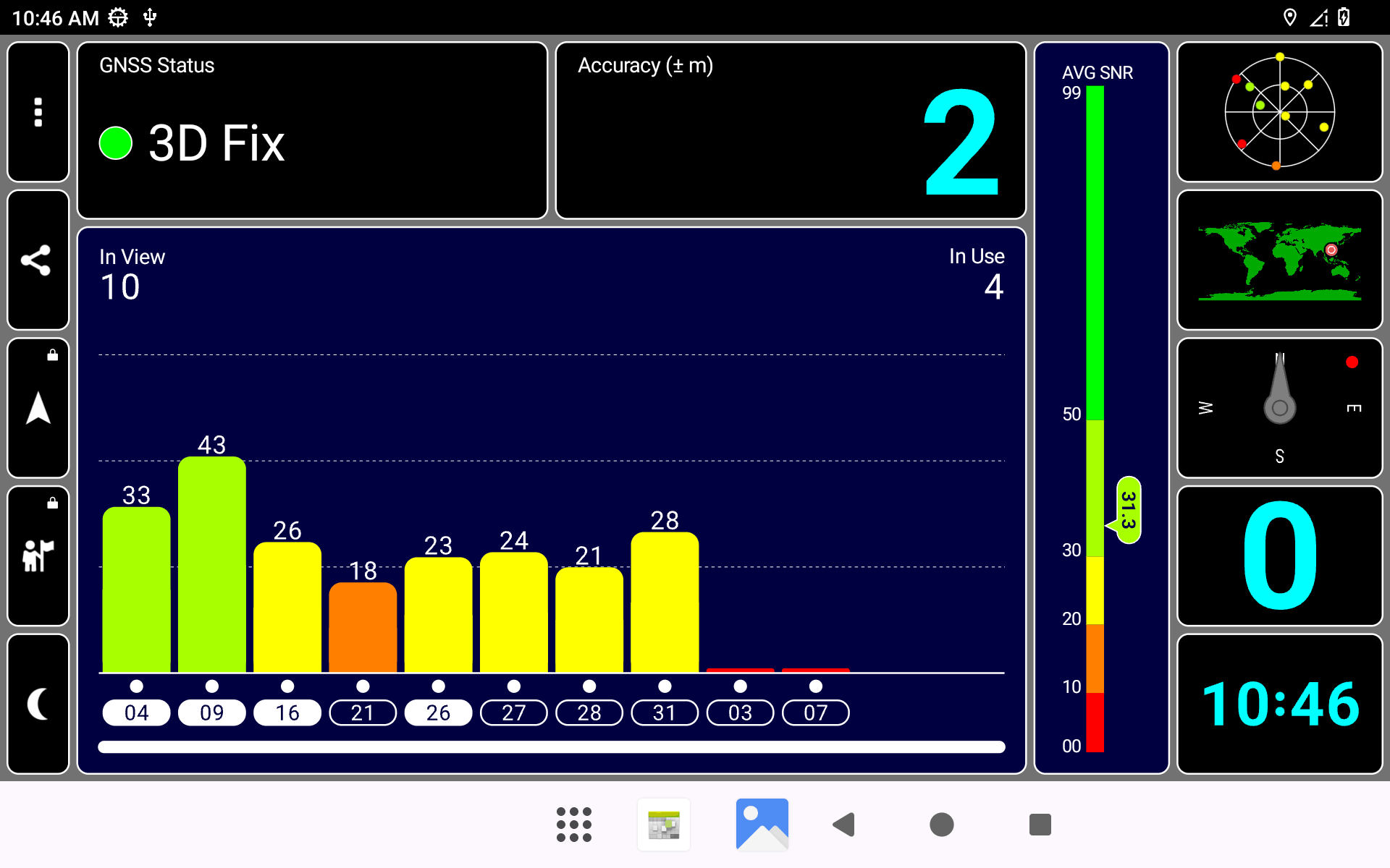
6.17.2 GPS
❶ Insert 4G module to PCIe socket.
❷ Connect GPS antenna.
❸ Power on. Click GPS Test to test.
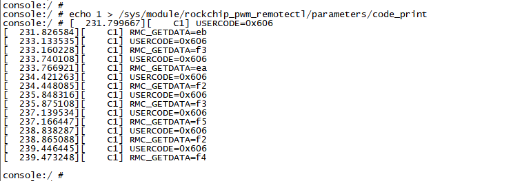
6.18 IR
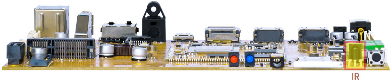
❶ Turn on IR.
echo 1 > /sys/module/rockchip_pwm_remotectl/parameters/code_print
❷ Press the Infrared controller, you can view the received datas on the terminal.